Failed to Connect to ESP32: No Serial Data Received
Fix 'Failed to connect to ESP32: No serial data received' step by step: data cable, drivers, ports, download mode on S3, C3 and XIAO, and the ESP32-CAM-MB.
- Author
 Mauro Brambilla
- Published
- Reading time
- 8 min
- Category
- Troubleshooting
In short
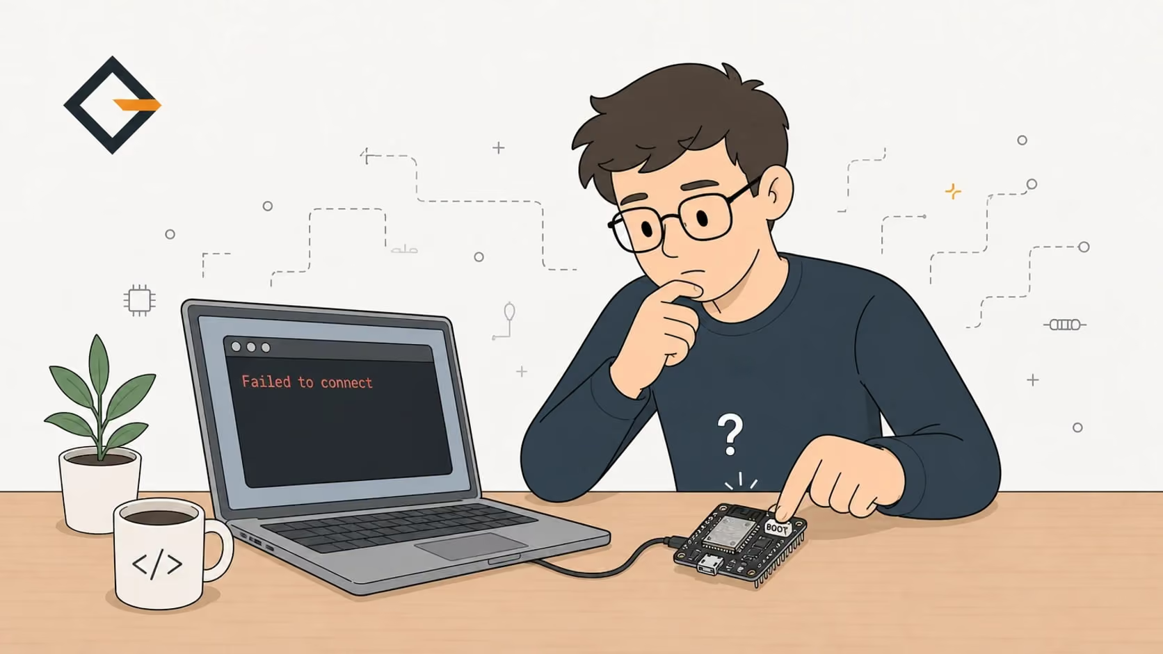
The error means esptool got no reply from the chip's ROM bootloader. Check the data cable and port first, then force download mode by hand: hold BOOT (GPIO0), tap RESET, and retry.
Failed to connect to ESP32: No serial data received means esptool opened the serial port but heard nothing back from the chip's ROM bootloader. Espressif ties it to the hardware side: a dead board, unconnected RX/TX lines, or a failed reset into download mode. In practice that usually comes down to a charge-only USB cable, the wrong or busy port, a board that never entered download mode, or a weak power supply. We'll go through them in that order, cheapest fix first.
This guide covers classic ESP32 dev boards, native-USB chips (ESP32-S3, C3, C6), the XIAO ESP32-S3 and the ESP32-CAM-MB board. The error text and causes come from Espressif's esptool troubleshooting page, and the board sequences are the ones the OpenGizmo projects use to flash their firmware from the browser.
What does "No serial data received" mean?
Download mode is the state where the ESP32's ROM bootloader waits for esptool over the serial port. The chip enters it when GPIO0 is held low at reset (the "BOOT" button does exactly that). Esptool sends sync packets, and the error appears when not one byte comes back. Espressif's docs say it "usually implies some kind of a hardware issue": a board that isn't working at all, RX/TX lines that aren't connected, or a problem resetting into download mode.
Current esptool (I checked the 5.1.0 and 4.8.1 sources) prints it like this:
A fatal error occurred: Failed to connect to ESP32: No serial data received.
For troubleshooting steps visit: https://docs.espressif.com/projects/esptool/en/latest/troubleshooting.htmlThe chip name changes with your target (ESP32-S3, ESP32-C3). Older posts may quote a different message for the same situation, such as "Timed out waiting for packet header". I couldn't find that string in the esptool 3.3.2, 4.8.1 or 5.1.0 sources, so I can't say which release printed it. If you see it, the fixes below still apply.
The browser flasher on the project pages is built on esptool-js 0.7.1, and when it can't reach the chip it shows "Failed to connect with the device". Same problem, shorter sentence, same fixes.
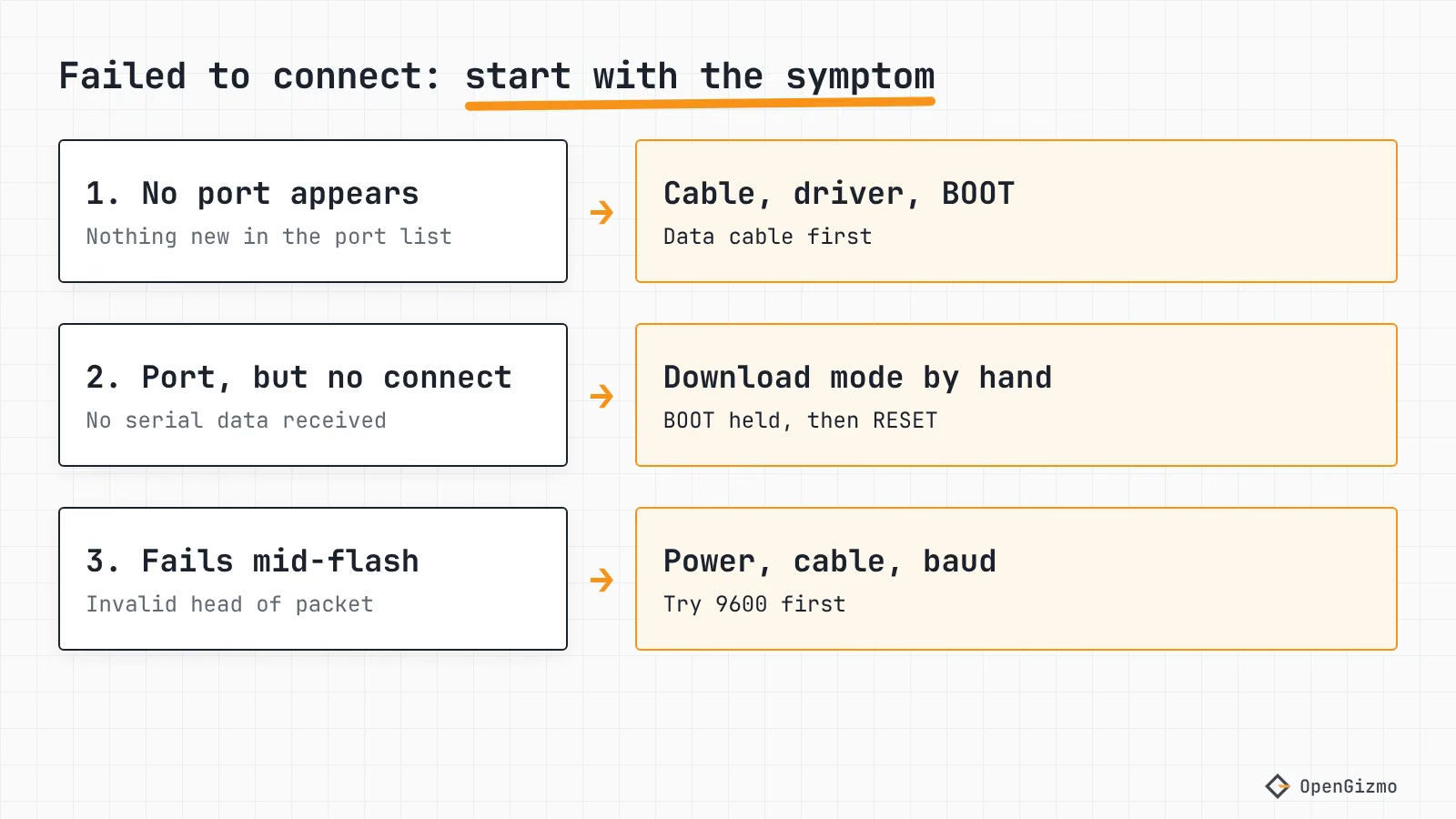
| What you see | Most likely cause | First thing to try |
|---|---|---|
| No new serial port when you plug the board in | Charge-only cable, missing driver, dead port | Swap the cable, change the USB port |
| Port appears, 'No serial data received' | Chip not in download mode, or another program holds the port | Close other terminals, then BOOT held + RESET |
| 'Wrong boot mode detected (0xXX)!' | Chip answers, but the auto-reset didn't work | Enter download mode by hand |
| 'Invalid head of packet (0xXX)' | Bad cable, breadboard shorts, brownout | Different cable, lower baud rate |
| Fails partway through flashing | Unstable power or baud rate too high | Retry at a lower baud rate |
1. Is it the cable? How do you spot a charge-only cable?
A charge-only cable has the power wires but not the data pair, so the board lights up and your computer sees nothing. Espressif's pages don't describe this case and I have no figure for how common it is, but the Gizmo Camera README lists "try another USB cable (some only charge)" among its first checks, and it costs nothing to try.
- Unplug the board and plug it back in. Look at the port list:
ls /dev/tty*on Linux,ls /dev/cu.*on macOS, Device Manager on Windows (Espressif's serial connection guide uses the same method: compare the list with and without the board). - If nothing new appears, try a cable that you know carries data, for example the one from a phone you sync with a computer.
- Plug it directly into the computer, not into a hub or a monitor's USB port.
You should now see a new entry. If you do, move on. If you don't, test the board with a second computer before blaming it.
2. Is it the driver or a permission problem?
Boards with a USB-to-UART bridge need the bridge chip's driver. Espressif's boot mode page names FTDI, CP210x and CH340x as the common converter chips, and its serial connection guide says the drivers are normally bundled with the operating system. If the port shows up in Device Manager with a warning icon, install the driver for the chip printed on your board.
Two more things hide a working board:
- Another program holds the port. A serial monitor left open in another window is the classic one, and on Linux
modem-managercan interfere too. Close them and retry. - Linux permissions. esptool needs read and write access to the port. Add your user to the
dialoutgroup (oruucpon some distributions), then log out and back in:
sudo usermod -a -G dialout $USER3. How do you enter download mode by hand?
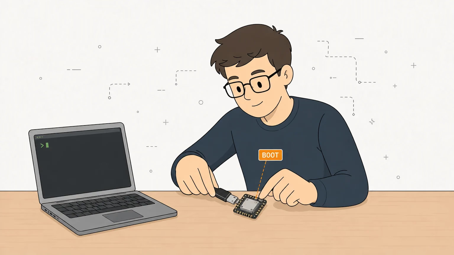
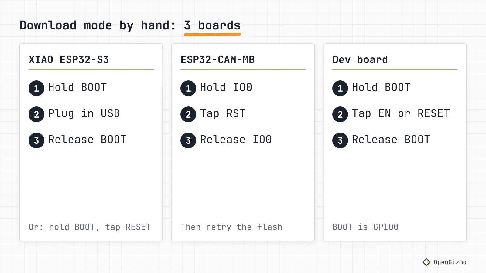
Most dev boards reset themselves into download mode: esptool toggles the DTR and RTS lines of the USB bridge, wired to GPIO0 and EN. When that circuit is missing, slow, or unreliable, you do it yourself. Espressif's boot mode page puts it as: hold the Boot button (GPIO0) and press EN. GPIO0 low at reset selects the ROM serial bootloader, and GPIO0 high (or floating, thanks to the internal pull-up) selects normal execution.
XIAO ESP32-S3
Seeed's getting started page documents two ways into bootloader mode, both with the BOOT and Reset buttons:
- Hold BOOT, connect the USB cable while holding it, then release BOOT.
- Or hold BOOT while powering up and press Reset once.
Seeed also says to try pressing Reset on its own first if the port is missing or the upload fails. Both buttons sit on top of the board, so with the enclosure of a XIAO-based device such as Gizmo Ticker closed, you can't reach them. My notes for the XIAO say the same: once it's closed, flash and reset it over USB. For a stubborn port, open the box and use the BOOT sequence on the bench.
ESP32-CAM on the ESP32-CAM-MB
The AI Thinker ESP32-CAM has no USB port: it sits on the ESP32-CAM-MB, a small USB adapter with IO0 and RST buttons. Gizmo Camera documents the manual sequence in its README: hold IO0, press and release RST, then release IO0 and flash again. IO0 is GPIO0, the same pin as BOOT. In the printed enclosure you press them with a paperclip through the pinholes in the long sides. The full walkthrough is in the ESP32-CAM-MB programming guide.
Generic dev board
Hold BOOT, press and release EN (often labeled RESET), release BOOT, and start the upload. Pins other than GPIO0 also matter for some chips: on the ESP32-S3, GPIO46 must be floating or low to enter the serial bootloader. The strapping pins by chip guide covers the rest.
4. Why does it fail on native-USB chips (ESP32-S3, C3, C6)?
Chips such as the ESP32-S3, ESP32-C3 and ESP32-C6 have a built-in USB Serial/JTAG controller, so there is no bridge chip between the computer and the ESP. Espressif says it "is able to put" the chip "into download mode automatically", so the bridge-related causes above mostly don't apply. A few others do:
- The firmware took the USB pins. The controller is fixed-function: it can't be reconfigured for anything except a serial port and JTAG. But if the application reconfigures or disables the USB pins (on the ESP32-S3 they are GPIO19 for D- and GPIO20 for D+, per Espressif's console guide), the device disappears from the computer. The fix is the manual sequence: pull the boot pin low (GPIO0 on the ESP32-S3, GPIO9 on the ESP32-C6) and reset the chip, then flash a sketch that leaves USB alone.
- Deep sleep. On the ESP32-S3, the USB Serial/JTAG device appears disconnected while the chip is in deep sleep and reconnects when it wakes. A sketch that sleeps almost all the time is hard to catch: use the BOOT sequence.
- The board won't restart after a manual download. If you entered download mode with BOOT and EN, esptool can't leave it with the default reset, because USB Serial/JTAG triggers only a core reset that doesn't re-read the boot pin. Add
--after watchdog-reset, or just press EN or replug the board.
The commands use the esptool 5 syntax (esptool, hyphenated write-flash); older 4.x releases spell it esptool.py and write_flash.
esptool --port /dev/ttyACM0 --after watchdog-reset write-flash 0x0 merged.binReplace the port and the file with yours. On Linux, native-USB boards usually show up as /dev/ttyACM* and bridge boards as /dev/ttyUSB*, though I haven't verified that for every board.
5. Power problems that look like flash errors
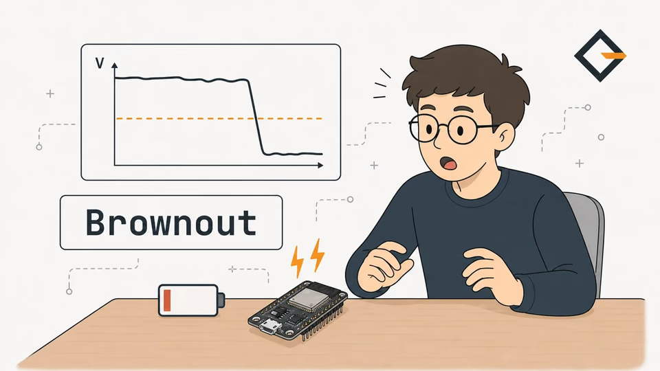
If the connection works but flashing dies halfway, or you see Invalid head of packet, suspect power and the cable. Espressif says the 3.3 V supply has to deliver up to 70 mA continuous with 200 to 300 mA peaks, and needs enough capacitance to ride out those spikes (esptool troubleshooting). It also warns that the 3.3 V output of FTDI FT232R adapters and Arduino boards does not supply enough current, and that very simple pin breakout modules don't integrate enough capacitance to work reliably without extra components.
Try, one at a time: a shorter or better cable, a different port, removing the board from the breadboard (breadboards can short the SPI flash pins), and unplugging anything on the GPIO pins. A brownout during flashing is the same story as the brownout detector reset, only earlier in the boot.
6. Last resorts: baud rate, chip flag and a trace
Still stuck? Change one thing at a time:
- Lower the baud rate. Espressif suggests
-b 9600as a very slow value to rule out a baud problem. Esptool's default is 115200, and the initial connection is limited to that. - Name the chip. Skipping autodetection with
--chip esp32s3removes one variable. - Trace the conversation.
esptool --tracedumps every serial exchange, which tells you whether anything comes back at all.
esptool --chip esp32s3 --port /dev/ttyACM0 --baud 9600 --trace flash-idflash-id reads the flash chip's ID without writing anything, so it's a safe test. If it answers, your connection is fine and the problem was in the flash step. If the connection works but you are unsure where the image lands in flash, the ESP32 partition table explained shows the layout.
What to remember
"No serial data received" is a communication failure, not a verdict on the firmware. Work down the list: data cable, port and permissions, download mode by hand (BOOT held, then RESET), then power and baud rate. The cable and the manual BOOT sequence are the first two things to rule out, but Espressif gives no statistics on which cause is most common, and a dead board or a damaged USB-UART chip is possible when everything else fails.
I didn't test the sequences on every board in this post. The XIAO and the ESP32-CAM-MB steps come from Seeed's wiki and the Gizmo Camera README, the rest from Espressif's documentation. Behavior can differ by board revision, bridge chip and operating system. Once the connection works, flashing from the browser is the quickest way to put a project on the board, and what an ESP32 is gives the background on the chips mentioned here. If you're on a XIAO ESP32-S3 and your sketch needs spare pins, the XIAO ESP32-S3 pinout guide shows which ones are safe.
Frequently asked questions
Find quick answers to the most common questions about this topic.
It means esptool opened the serial port but received no bytes back from the ESP32's ROM bootloader. Espressif's troubleshooting page says this usually points to a hardware problem: a charge-only cable, unconnected RX/TX lines, a dead board, or a failed reset into download mode.

Author
Mauro BrambillaReady to build your own gizmo?
Pick an open-source ESP32 project and follow its step-by-step guide, from the parts list and wiring to the firmware and the first boot.