ESP32 Brownout Detector Was Triggered: Causes and Fixes
Why the ESP32 resets with 'Brownout detector was triggered', how to find the weak link in the power path, and the fixes that work on dev boards and ESP32-CAM.
- Author
 Mauro Brambilla
- Published
- Reading time
- 8 min
- Category
- Troubleshooting
In short
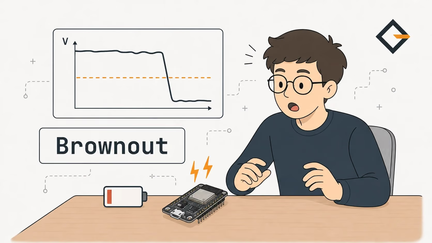
The brownout reset means the ESP32's supply dipped below the detector's threshold, usually during a Wi-Fi burst or flash LED pulse. Fix the cable, port or decoupling, not the detector.
Brownout detector was triggered is the message an ESP32 prints just before it resets itself because its supply voltage fell below the detector's threshold. A brownout is a dip in supply voltage that does not cut power completely but is low enough to make a chip unreliable. On an ESP32 or ESP32-CAM it usually happens when Wi-Fi or a flash LED suddenly draws more current than the USB port, cable or regulator can deliver.
Is your board stuck in a reset loop with that line scrolling in the serial monitor? Let's find the weak link in the power path, fix it, and leave the detector switched on. The facts below come from the ESP-IDF sources, the ESP32 datasheet and Espressif's hardware design guidelines, plus what the Gizmo Camera and Gizmo Ticker firmware really do. I did not measure any rail with a scope, so I quote measured numbers only from their sources.
What does "Brownout detector was triggered" mean?
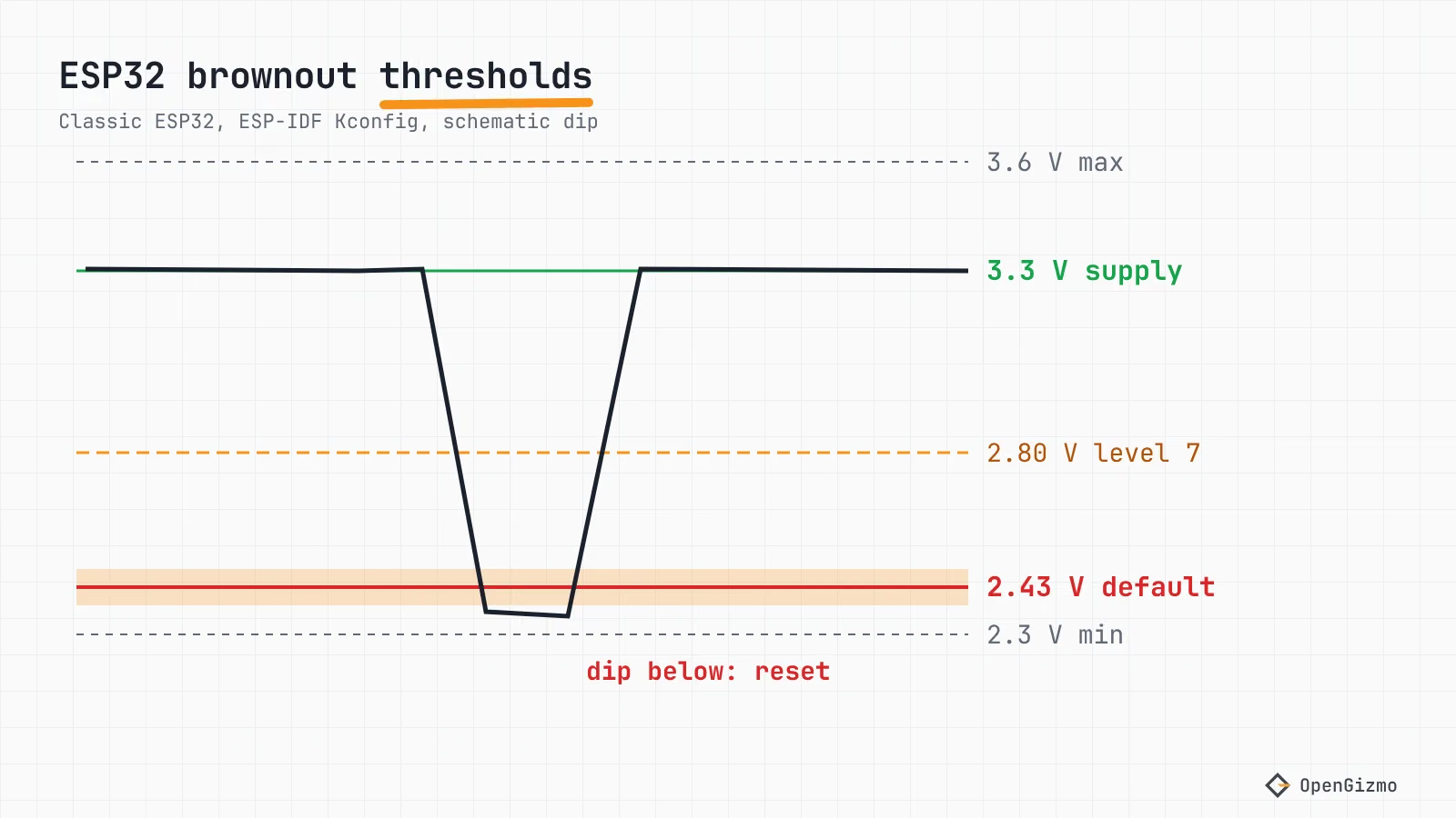
The ESP32 has a hardware detector that compares its supply voltage with a threshold. ESP-IDF's Kconfig (v5.5) describes option CONFIG_ESP_BROWNOUT_DET, "Hardware brownout detect & reset", like this: the detector can tell if the voltage is lower than a specific value and, if so, "it will reset the chip in order to prevent unintended behaviour". It is on by default.
The exact line comes from brownout.c in ESP-IDF: Brownout detector was triggered. That file prints it in the interrupt-based mode, where the handler logs the message, flushes the UART and then resets the system by software. Per the Kconfig, this mode exists for first-revision classic ESP32 chips, whose direct brownout reset does not work (ESP32 errata 3.4), and for code that needs to do something before the restart. Either way the reset reason reads as a brownout: ESP-IDF names it ESP_RST_BROWNOUT, and the Arduino-ESP32 reset reason page calls it RTCWDT_BROWN_OUT_RESET, "Reset when the vdd voltage is not stable".
Which voltage triggers it?
The level is selectable at build time and differs by chip. These values are from the Kconfig files of ESP-IDF v5.5, which call them estimates that vary between chips:
| Chip | Default level | Default threshold (V) | Selectable range (V) |
|---|---|---|---|
| ESP32 | ESP_BROWNOUT_DET_LVL_SEL_0 | 2.43 ± 0.05 | 2.43 to 2.80 |
| ESP32-S3 | ESP_BROWNOUT_DET_LVL_SEL_7 | 2.44 | 2.44 to 3.30 |
| ESP32-C3 | ESP_BROWNOUT_DET_LVL_SEL_7 | 2.51 | 2.51 to 3.27 |
For comparison, the ESP32 datasheet (v5.3) gives an operating voltage of 2.3 V to 3.6 V, and recommends 3.3 V from a supply that can deliver 500 mA or more. So the default detector fires only a little above the chip's own minimum. That is a useful hint: the rail did not just run a little low, it fell to within a few tenths of a volt of the chip's own minimum.
Why does the ESP32 reset when Wi-Fi starts?
Because the radio is the biggest sudden load. The ESP32 datasheet (Table 5-4) lists a typical 240 mA while transmitting 802.11b at +19.5 dBm and 180 mA for 802.11n MCS7, measured with a 50% duty cycle, so bursts can be higher than the averages. Espressif's hardware design guidelines say that when the ESP32 transmits there may be a sudden current increase "causing power rail collapse", and recommend at least 10 µF at the main power entrance and 0.1 µF close to the digital supply pins. Those capacitor values are written for board designers, but they show where the problem sits: the current spike has to come from somewhere close to the chip.
The chip is never alone, so the other loads add up:
- ESP32-CAM: the camera runs from the same supply, and the on-board flash LED is on GPIO4 (Random Nerd Tutorials). The Gizmo Camera firmware turns that LED on, waits 150 ms so the exposure can adapt, then takes the frame, and it keeps the Wi-Fi radio awake with
WiFi.setSleep(false). Its README lists the board restarting "when the flash fires or during Wi-Fi setup" as a brownout. - LED matrix: the Gizmo Ticker feeds its MAX7219 matrix from the XIAO ESP32-S3's 5 V pad, and its brightness (intensity 0 to 15) is a setting in the web app. A bright matrix plus Wi-Fi is a bigger load than the chip alone. I have not measured its current, and the wiring is covered in MAX7219 FC16 with ESP32.
- Flashing: esptool says the 3.3 V supply must handle "up to 70mA continuous, 200-300mA peak" and have enough capacitance (esptool troubleshooting), and that "the chip might be browning out" on an "Invalid head of packet" error. The failed-to-connect guide covers that side.
Where is the weak link in the power path?
The detector looks at the chip's supply, so it cannot tell you which part upstream is guilty. The 5 V from the USB port goes through the cable, the board's connector and regulator, and only then reaches the chip.
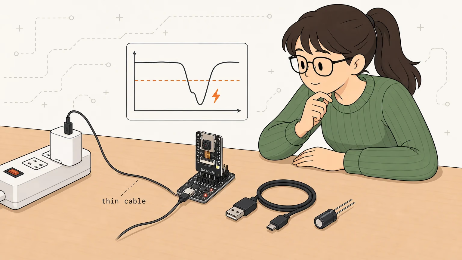
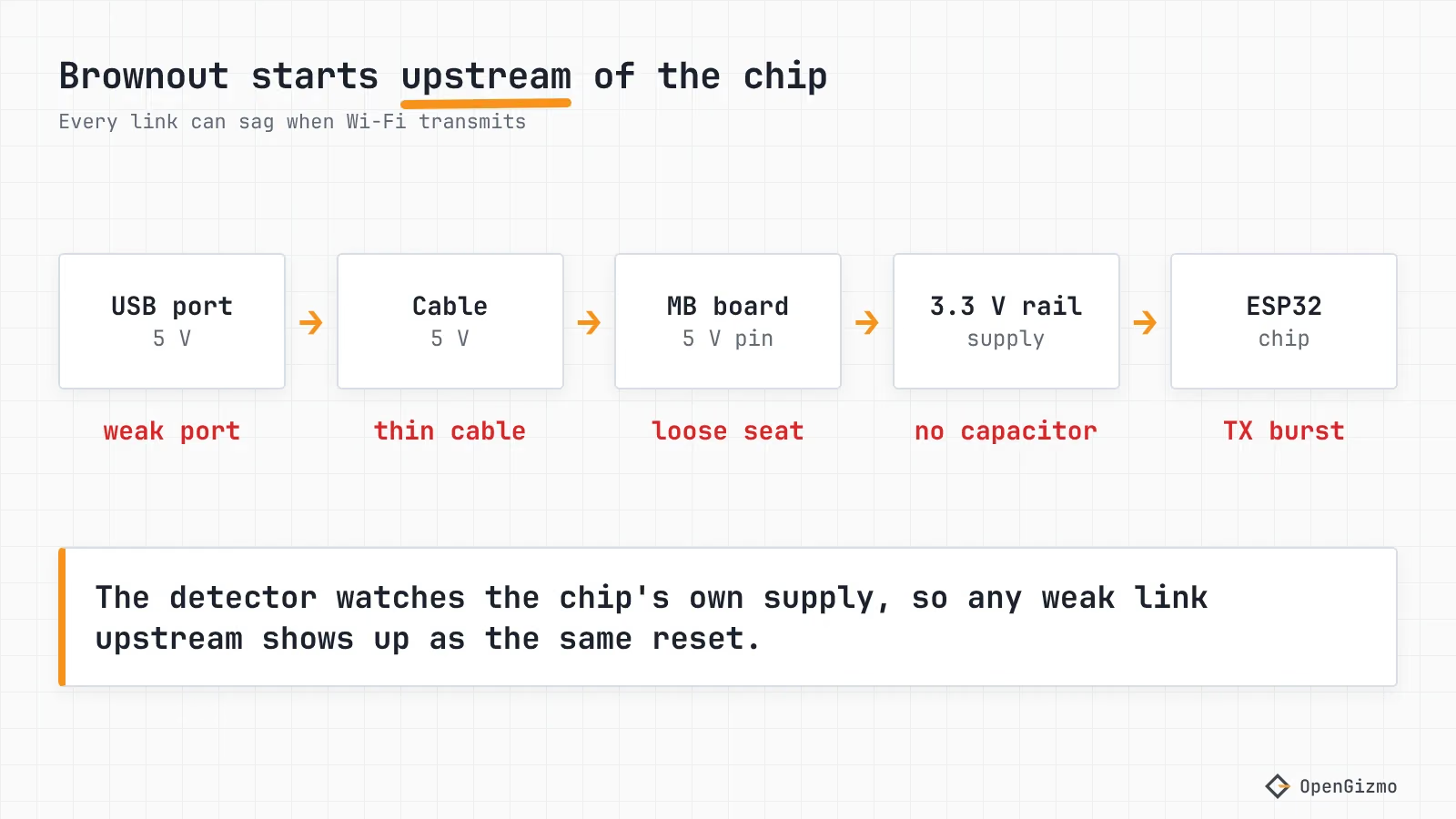
Change one thing at a time and re-test with the same trigger (for example, taking a snapshot with the flash on):
- Swap the cable. Use a short, thick data cable. Makerguides recommends short thick wires (22 AWG or thicker), and espboards.dev a 24 AWG power pair. A thin cable drops voltage under load, and it is the cheapest thing to try.
- Change the port. A laptop port or an unpowered hub may limit current, and the datasheet asks for a supply that can deliver 500 mA or more. Try a wall charger or a powered hub.
- Remove the breadboard and the extras. Makerguides advises against powering through breadboards. Unplug displays, LEDs and sensors, and see whether the reset stops.
- Seat the board properly. On the ESP32-CAM, 5 V and GND pass through the pin rows of its USB carrier, so a half-seated module may sag, which I have not measured. The ESP32-CAM-MB programming guide shows the seating.
- Use the 5 V pin on a bare ESP32-CAM. Random Nerd Tutorials says many people reported errors powering it from 3.3 V and advises the 5 V pin.
You should see the reset loop stop, or at least come later in the boot. If it stops after a change, keep that change and move on to the next step only if it comes back.
Does the ESP32-CAM-MB board help or hurt?
It helps with convenience and does not add capacity: it is a micro-USB socket and a serial chip, so you are still limited by the cable and port behind it. I could not find the MB board's schematic, so I do not know its regulator or capacitors and cannot say how its revisions differ. If a camera works on one port and browns out on another, the port is the variable.
Which fix works: capacitor or external supply?
Both can help, and they solve different problems. A bulk capacitor is a large capacitor placed across the supply that supplies the short bursts the source cannot. Makerguides suggests 470 µF or more between 5 V and GND (watch the polarity), plus a 0.1 µF ceramic; espboards.dev suggests 470 to 1000 µF low-ESR placed close to the board, with a 0.1 µF in parallel. These are community recommendations, not Espressif numbers, so treat them as a starting point.
| Cause | Typical sign | Fix | Effort |
|---|---|---|---|
| Thin or long cable | Resets on Wi-Fi start or flash LED | Short, thick data cable | Low |
| Weak USB port or hub | Works on a charger, not on a laptop | Powered port or 5 V adapter of 1 A or more | Low |
| Loose seat or breadboard | Resets when you touch the board | Reseat, remove the breadboard | Low |
| Too much load | Resets at full LED brightness or with the flash | Lower brightness, remove loads | Low |
| Spiky load on a marginal supply | Resets only in short bursts | 470 µF or more across 5 V and GND, near the board | Medium |
| Damaged regulator | Resets on every supply you try | Replace the board | Medium |
A 1 A regulated 5 V adapter is the minimum Makerguides and espboards.dev both give for the ESP32-CAM, and Makerguides suggests 2 A. If your project drives an LED matrix like the ticker's, turning its intensity down is a quick test for the load: if the resets stop, the supply was marginal.
Should you disable the brownout detector?
No, not as a fix. Disabling it, with CONFIG_ESP_BROWNOUT_DET set to n in the ESP-IDF configuration, or with the popular Arduino line that writes 0 to RTC_CNTL_BROWN_OUT_REG, stops the reset and the message. It does not give the chip more voltage. The detector exists, in Espressif's words, "to prevent unintended behaviour", so without it the chip keeps running while its supply is below the level it was reset for. Makerguides itself warns this does not fix the power problem and may cause flaky Wi-Fi, camera failures or noisy video.
Switching it off is reasonable in only one case: a short diagnostic run, to see whether the rest of the code works, as long as you re-enable it afterwards.
The level option, CONFIG_ESP_BROWNOUT_DET_LVL_SEL, is no escape either. On the classic ESP32, ESP32-S3 and ESP32-C3 the default is already the lowest level in the list, so the option can only make the chip reset earlier. Those options belong to ESP-IDF projects: the Arduino core ships a prebuilt configuration, and I did not check which level the camera's core uses.
If you cannot find the weak link, reduce the load instead: espboards.dev suggests lowering the CPU frequency with setCpuFrequencyMhz(80) or using deep sleep when idle (see ESP32 deep sleep current draw).
How do you tell a brownout from a bad camera ribbon (0x105)?
Read the log. A brownout prints Brownout detector was triggered and resets the chip, over and over. The camera error is a different line from the camera driver: Camera probe failed with error 0x105(ESP_ERR_NOT_FOUND). ESP-IDF defines 0x105 as "Requested resource not found", and in the esp32-camera driver it is logged when the probe of the sensor fails. In other words, the chip is running fine but found no camera.
In the Gizmo Camera firmware, a failed camera start does not reset anything: the firmware keeps running so the web app can say what is wrong, and shows "Camera not found". The README's fix is to power the board off, check that the ribbon is fully inserted and its latch closed, and power it on again. I found no source that ties 0x105 to a brownout, so treat them as separate problems. Fix the ribbon first if you see 0x105 without a brownout line, and the power path first if you see the brownout line. The GPIO pin guide for the ESP32-CAM explains which pins the camera takes.
What to remember
The brownout detector is the messenger. "Brownout detector was triggered" means the chip's supply crossed a threshold of roughly 2.4 to 2.5 V on the ESP32, S3 and C3 defaults, usually when Wi-Fi or a flash LED added load to a weak cable, port or contact. Work from the cheapest change: cable, port, seating, load, then a bulk capacitor or a 1 A or better 5 V adapter.
What I did not verify: measured current for the Gizmo Camera or the ticker, the ESP32-CAM-MB schematic, and the capacitor values beyond what the linked sources recommend. Results also vary with board revision and chip. Once the camera stays up, the next step is one HTTP request that returns a JPEG, or the ESP32-CAM-MB guide if you are still wrestling with the board itself.
Frequently asked questions
Find quick answers to the most common questions about this topic.
You can, but it hides the symptom and keeps the cause. The detector resets the chip when the supply drops below its threshold, so without it the ESP32 keeps running on a sagging rail, with flaky Wi-Fi, camera failures or noisy video as the usual result. Fix the cable, port or decoupling instead.

Author
Mauro BrambillaReady to build your own gizmo?
Pick an open-source ESP32 project and follow its step-by-step guide, from the parts list and wiring to the firmware and the first boot.