ESP32 I2C LCD 16x2 Not Working: Address, 5 V, Contrast
ESP32 I2C LCD 16x2 blank or showing blocks? Scan for the 0x27 or 0x3F address, turn the contrast trimmer, and check the 5 V backpack on 3.3 V pins.
- Author
 Mauro Brambilla
- Published
- Reading time
- 8 min
- Category
- Troubleshooting
In short
A blank ESP32 I2C LCD is usually the address (0x27 for a PCF8574 backpack, 0x3F for a PCF8574A), the contrast trimmer, or 5 V signals on a 3.3 V pin. Scan the bus first, then adjust.
An ESP32 I2C LCD 16x2 that stays blank is usually one of three things: the wrong I2C address (0x27 for a PCF8574 backpack, 0x3F for a PCF8574A), a contrast trimmer turned the wrong way, or the 5 V backpack's signal levels meeting a 3.3 V ESP32 pin. Scan the bus first, then adjust the trimmer.
The Gizmo Reolink Switch runs a 16x2 LCD with an I2C backpack on a XIAO ESP32-S3, so the pins, library versions and code below come from its open-source firmware, and the chip facts come from the Texas Instruments, Espressif and hd44780 library sources. I did not test faulty boards for this post, and I say so where it matters.
Why is my ESP32 I2C LCD lit but blank?
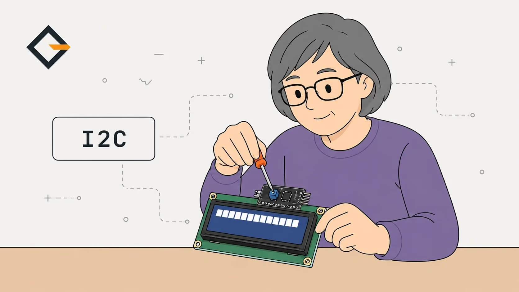
An I2C backpack is the small board soldered on the back of a 16x2 character LCD. It holds a PCF8574 chip, an I2C expander that turns the LCD's parallel pins into two wires (SDA and SCL), and a blue trimmer for the contrast. Lit but blank means the backlight has power, so the problem is one of the six causes below. Check them in this order, because each test takes under a minute.
| Symptom | Likely cause | Test |
|---|---|---|
| Backlight on, no characters | Contrast trimmer at the wrong setting | Turn the trimmer slowly, a quarter turn at a time |
| Backlight on, top row of solid blocks | LCD powered but not initialized | Run the I2C scanner, then check the sketch and the contrast |
| Scanner finds nothing | SDA and SCL swapped, loose wire, no pull-ups | Check the wiring against the pins below, then re-scan |
| Scanner finds 0x3F, sketch uses 0x27 | Address mismatch | Use the address the scanner printed |
| Backlight off too | No 5 V on the backpack | Measure VCC and GND at the backpack pins |
| Random characters or flicker | Noise, long wires or full-screen clears | Shorten the wires, rewrite rows instead of clearing |
The row of blocks matters. It is commonly described as the sign of a powered LCD that never received its setup commands, but I could not find a datasheet line that says so, so treat it as a hint, not a rule. The scanner in the next section settles it.
1. Find the address with an I2C scanner
An I2C address is the 7-bit number a device answers to on the bus. The scanner asks every address from 1 to 126 whether anyone is home. In the Arduino Wire library, endTransmission() returns 0 when a device acknowledged. In the Arduino-ESP32 core's Wire.cpp, the ESP-IDF "not found" and "fail" results both map to return value 2, and a timeout maps to 5 (checked in the source as of November 2026).
#include <Wire.h>

void setup() {
    Serial.begin(115200);
    delay(2000); // Give the USB serial monitor time to attach
    Wire.begin(5, 6); // XIAO ESP32-S3: SDA = D4 (GPIO5), SCL = D5 (GPIO6)
    Wire.setClock(100000);
}

void loop() {
    uint8_t found = 0;
    for (uint8_t address = 1; address < 127; address++) {
        Wire.beginTransmission(address);
        if (Wire.endTransmission() == 0) {
            Serial.printf("Device at 0x%02X\n", address);
            found++;
        }
    }
    if (found == 0) Serial.println("No I2C device found: check wiring and power");
    delay(3000);
}Open the serial monitor at 115200 baud. With the backpack connected you should see one line, usually Device at 0x27 or Device at 0x3F. Your address may differ, and that is the point of scanning. If the line is 0x38 to 0x3E or 0x20 to 0x26, the backpack's address pads (A0, A1, A2) are set differently from the common default.
Why 0x27 on one backpack and 0x3F on another?
The two addresses come from two chip variants. Texas Instruments' PCF8574 datasheet (revision of September 2024) defines the address as 0100 A2 A1 A0, which gives 0x20 to 0x27. The PCF8574A datasheet defines 0111 A2 A1 A0, which gives 0x38 to 0x3F. With all three address pins high, the PCF8574 sits at 0x27 and the PCF8574A at 0x3F.
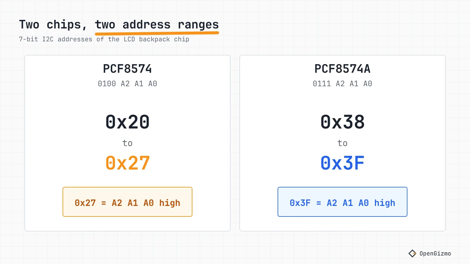
So a sketch that hardcodes 0x27 will find nothing on a PCF8574A board. Change the number to the one the scanner printed, or let the library find it, as the next section shows.
Once the scanner sees the backpack, a minimal sketch with the hd44780 library (the same one the Reolink Switch uses) proves the display works. It finds the address by itself:
#include <Wire.h>
#include <hd44780.h>
#include <hd44780ioClass/hd44780_I2Cexp.h>

hd44780_I2Cexp lcd; // Autolocates the backpack and its pin mapping

void setup() {
    Wire.begin(5, 6); // XIAO ESP32-S3: SDA = D4, SCL = D5
    if (lcd.begin(16, 2) != 0) return; // Non-zero: no display found
    lcd.print("Hello, I2C");
}

void loop() {}If the scanner finds the device but this sketch prints nothing, go to the contrast trimmer in step 2.
What does the Reolink Switch do about the address?
This is a detail I only found by reading the code. config.cpp defines DISPLAY_I2C_ADDRESS = 0x27, and the README says the backpack is "detected at 0x27". But a search of the firmware finds the constant only in its definition and its declaration: nothing reads it. display.cpp creates a plain hd44780_I2Cexp display;, and the header of the hd44780 library lists that no-argument form as "autolocate/autoconfigure everything". The firmware pins version 1.3.2 in its platformio.ini.
In practice, a 0x3F backpack should work with this firmware without a code change, because the library probes for it. I have not tried a PCF8574A board with the switch, so that is a reading of the code, not a test. If the library finds no device, display.begin() returns a non-zero status, and the firmware's initDisplay() returns quietly with the display marked not ready. The LCD stays dark and the rest of the switch keeps running, which is why a missing screen can look like a dead board.
2. Turn the contrast trimmer
The contrast trimmer is the small blue potentiometer on the backpack. It sets the voltage that decides how dark the characters appear, so a wrong setting gives a lit screen with nothing readable, or every cell filled in. The hd44780 library's own diagnostic sketch, I2CexpDiag, prints this advice to the serial monitor: "If all pixels are on, or no pixels are showing, but backlight is on, try adjusting contrast pot".
Use a small screwdriver and turn it a quarter turn at a time, pausing to look. Do this while the sketch is running and the display has been initialized, otherwise you only learn about the contrast of an empty screen. If one end of the range shows a row of blocks and the other end shows nothing, text should appear somewhere in between.
I2CexpDiag is worth running if the scanner finds the device and the text still will not show. By its own description it scans the bus, tries to initialize each display, blinks the backlight and reports missing pull-ups. Its changelog also mentions a check for SDA and SCL shorted together.
3. Does a 5 V LCD backpack work with a 3.3 V ESP32?
Often, but it is outside what the datasheets guarantee, and the reason is the pull-up resistors. I2C lines are open-drain: devices only pull them low, and a pull-up resistor lifts them to the high level. The Arduino-ESP32 I2C documentation says the lines "require pull-up resistors", and the ESP32-S3's internal weak pull-up is typically 45 kΩ (Table 5-4 of the Espressif datasheet, v2.2), which I read as too weak to rely on for I2C. So the pull-ups live on the backpack, and the question is what they connect to.
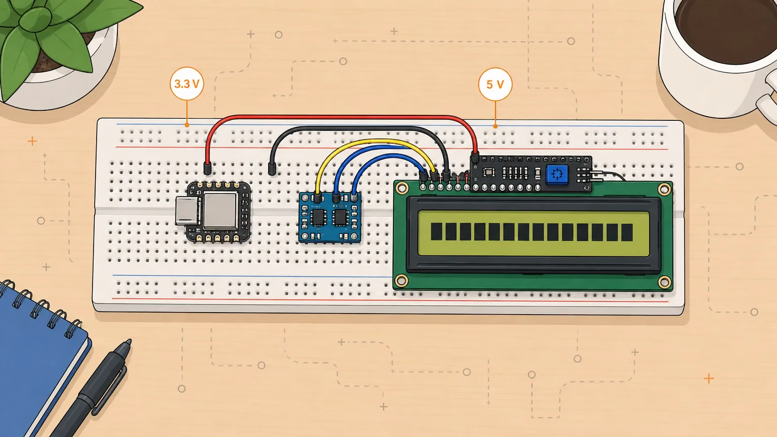
The hd44780 library's author warns about exactly this in the I2CexpDiag header, and notes that many backpacks carry 5 V pull-ups:
WARNING: 3v only systems like ARM/Teensy3/ESP8266 devices will need to take precautions on SDA and SCL connections if using 5V I2C devices.
Here are the numbers. The ESP32-S3's input high level may reach at most VDD + 0.3 V, about 3.6 V, in Table 5-4. If the backpack's pull-ups go to 5 V, SDA and SCL idle near 5 V, above that range. The PCF8574 on the other side needs a high of at least 0.7 × VCC (3.5 V at 5 V), according to its datasheet, and the ESP32-S3 guarantees only 2.64 V for its own high output. The 2.64 V output level only matters if a pin drives the line high itself, which open-drain I2C normally avoids.
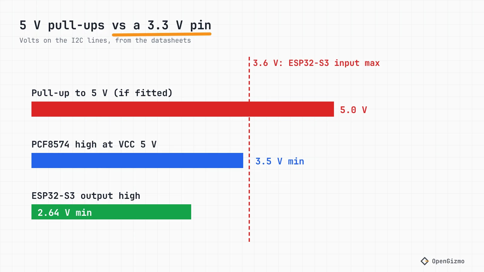
What the Reolink Switch does is documented in its README: the LCD is powered from the XIAO's 5V pad, and SDA and SCL go to D4 and D5 with nothing in between. The README gives no margin analysis, and I did not measure the voltage on the lines or look at which rail the pull-ups of the switch's module use, so I cannot say it is within spec. Seeed's wiki describes the 5V pad as 5 V out from the USB port, so that is what the LCD runs from.
You have four ways out, from safest to riskiest:
- Put a bidirectional I2C level shifter between the ESP32 and the backpack. This is the option that stays inside every datasheet.
- Power the backpack from 3.3 V. The PCF8574 accepts 2.5 to 6 V, but many 16x2 LCDs are specified for 5 V, so check your module and expect a dim or blank screen if it is not.
- Move the backpack's pull-ups to 3.3 V. The library author calls this a cheat that needs a hardware modification, and a 3.3 V high is below the PCF8574's 3.5 V minimum at a 5 V supply.
- Leave it as it is, if it works, and accept that you are outside the guarantee.
The same trade-off appears on the other OpenGizmo display: the 3.3 V logic section of MAX7219 FC16 With ESP32 walks through it with its own datasheet numbers.
4. Check the I2C pins on the XIAO ESP32-S3
On a generic ESP32, the Arduino-ESP32 documentation lists SDA on GPIO21 and SCL on GPIO22, but it says the defaults vary by board. On the Seeed Studio XIAO ESP32-S3, the wiki gives SDA on D4 (GPIO5) and SCL on D5 (GPIO6), and the core's board definition sets SDA to 5 and SCL to 6. So Wire.begin() with no arguments lands on D4 and D5, but a sketch that hardcodes GPIO21 and GPIO22 talks to the wrong pads.
The Reolink Switch avoids the question by passing both pins in initDisplay(): Wire.begin(config::DISPLAY_SDA_PIN, config::DISPLAY_SCL_PIN), followed by Wire.setClock(100000), which is 100 kHz, the standard I2C speed. The whole pad map is in XIAO ESP32-S3 Pinout: Which Pins Are Safe to Use.
| Signal | XIAO ESP32-S3 pad | GPIO | Backpack pin |
|---|---|---|---|
| I2C data | D4 | 5 | SDA |
| I2C clock | D5 | 6 | SCL |
| Power | 5V | - | VCC |
| Ground | GND | - | GND |
Double-check SDA and SCL are not swapped. A swapped pair is silent: the scanner prints your "No I2C device found" line, the same as a missing wire.
5. Why does the LCD text corrupt or flicker?
Garbled characters point at the bus or the supply, and flicker usually points at the software. They get separate fixes.
- Flicker: clearing the whole screen before every update makes the LCD blink. The Reolink Switch's
display.cppcomment says its rows are padded with spaces so old text is overwritten "without a clear, which makes the LCD flicker". Do the same: rewrite each row at full width. - Corrupt characters: shorten the SDA and SCL wires, push the breadboard jumpers in properly, and keep the clock at 100 kHz. A slow bus is the cheapest thing to try first, because you change one number.
- Characters change when Wi-Fi starts: the supply may be dipping on transmit bursts. The brownout detector guide covers how to find the weak link in the power path.
What did we verify, and what is still open?
You now have a scan that finds the backpack, the two address ranges with their datasheet source, the trimmer check, and the 5 V question with its numbers. The pins, the pinned library version, the 100 kHz clock and the autolocating constructor come from the Reolink Switch firmware. The address ranges and the thresholds come from the TI and Espressif datasheets, as of November 2026.
Four limits remain. I did not test a PCF8574A board with the switch. I did not measure the voltage on SDA and SCL, and I do not know which rail the pull-ups of the switch's module use, since backpacks differ. The "row of blocks" reading is common advice, not a datasheet line. And the 5 V case is outside the guarantee, so a level shifter is the safe fix. For the full build around this screen, read Control a Reolink NVR with an ESP32, or see the Gizmo Reolink Switch project page.
Frequently asked questions
Find quick answers to the most common questions about this topic.
A lit but blank 16x2 LCD usually has working power but a wrong address, a contrast trimmer set too low or too high, or an initialization that failed. Run an I2C scanner to confirm the backpack answers, then turn the blue trimmer on the backpack slowly until the characters appear.

Author
Mauro BrambillaReady to build your own gizmo?
Pick an open-source ESP32 project and follow its step-by-step guide, from the parts list and wiring to the firmware and the first boot.