XIAO ESP32-S3 Pinout: Which Pins Are Safe to Use
XIAO ESP32-S3 pinout: D0 to D10 mapped to GPIO, the default I2C, SPI and UART pads, the one strapping pad to avoid, and two real firmware pin maps.
- Author
 Mauro Brambilla
- Published
- Reading time
- 9 min
- Category
- Guides
In short
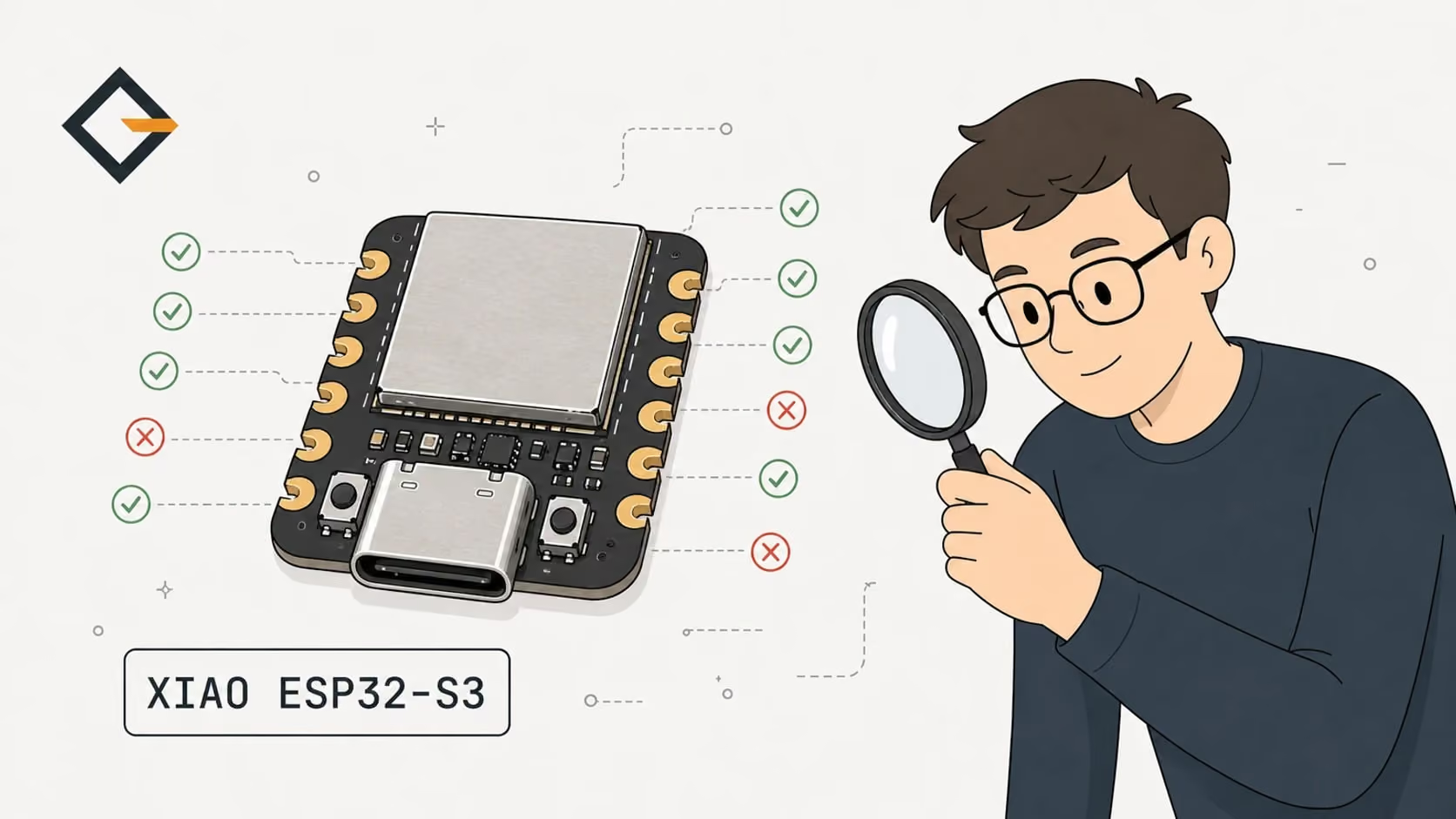
The XIAO ESP32-S3 has 11 GPIO pads, D0 to D10. D0, D1 and D3 are plain GPIOs, D4 and D5 are I2C, D8 to D10 are SPI, D6 and D7 are UART, and D2 (GPIO3) is the only strapping pin to avoid.
The Seeed Studio XIAO ESP32-S3 has 11 GPIO pads, D0 to D10. The safest picks are D0, D1 and D3 (GPIO1, GPIO2 and GPIO4) for a button or a buzzer, D4 and D5 for I2C, and D8 to D10 for SPI. Leave D2 (GPIO3, a strapping pin) free, and keep D6 and D7 for serial if you can.
You have a tiny board, 14 pads, and a part you want to wire without a surprise at boot. This guide maps every pad to its ESP32-S3 GPIO, flags the ones with a catch, and shows the two real pin maps behind the Gizmo Ticker and the Gizmo Reolink Switch. The numbers come from Seeed Studio's wiki, the ESP32-S3 datasheet (version 2.2) and the firmware repositories, and I mark what I could not verify at the end.
What is the XIAO ESP32-S3 pinout (D0 to D10 to GPIO)?
The XIAO ESP32-S3 breaks out 14 pads: three power pads (5V, GND, 3V3) and eleven GPIO pads labeled D0 to D10. The D label is Seeed's name for the pad, and the GPIO number is the chip's own. Your code can use either: in the Arduino core's pins_arduino.h for this board, D0 is a constant equal to 1 (GPIO1), and the Reolink Switch firmware below uses the plain GPIO numbers.
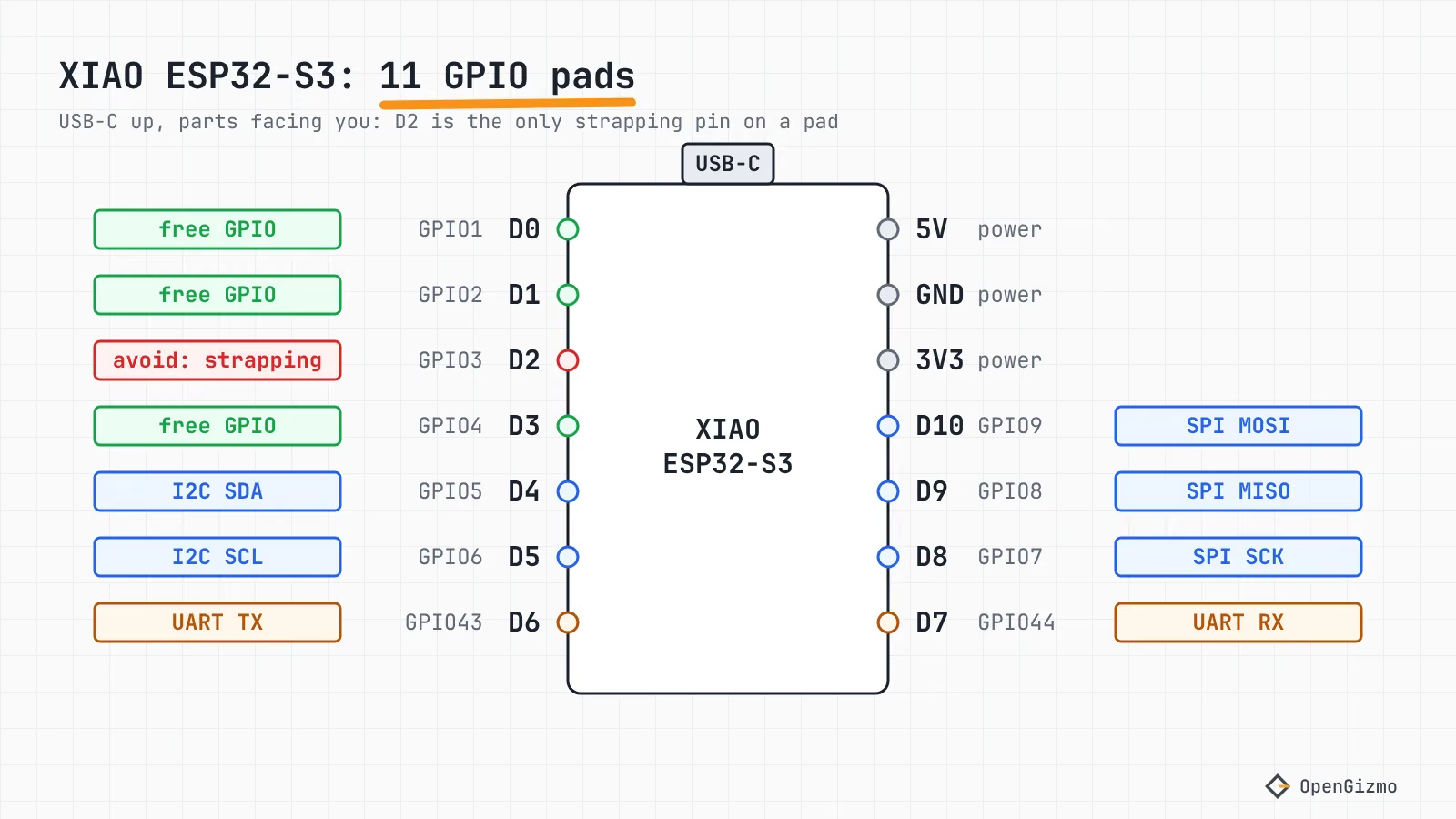
With the USB-C port up and the components facing you, D0 to D6 run down the left edge, and the right edge reads 5V, GND, 3V3, D10, D9, D8, D7. The table adds what each pad can do. ADC and touch come from the datasheet's pin list: GPIO1 to GPIO10 are on ADC1, and GPIO1 to GPIO14 have touch sensing. Two things are not on a pad at all: the BOOT and RESET buttons, and the user LED on GPIO21, which per Seeed's wiki lights when the pin is LOW.
| Pad | GPIO | Default function | ADC / touch | Verdict |
|---|---|---|---|---|
| D0 | 1 | none | ADC1, touch 1 | Safe: free GPIO |
| D1 | 2 | none | ADC1, touch 2 | Safe: free GPIO |
| D2 | 3 | none | ADC1, touch 3 | Avoid: strapping pin |
| D3 | 4 | none | ADC1, touch 4 | Safe: free GPIO |
| D4 | 5 | I2C SDA | ADC1, touch 5 | Safe, best kept for I2C |
| D5 | 6 | I2C SCL | ADC1, touch 6 | Safe, best kept for I2C |
| D6 | 43 | UART TX | none | Caution: serial pad |
| D7 | 44 | UART RX | none | Caution: serial pad |
| D8 | 7 | SPI SCK | ADC1, touch 7 | Safe, best kept for SPI |
| D9 | 8 | SPI MISO | ADC1, touch 8 | Safe, best kept for SPI |
| D10 | 9 | SPI MOSI | ADC1, touch 9 | Safe, best kept for SPI |
Two more pins have D labels in Seeed's table, D11 (GPIO42) and D12 (GPIO41), but they are not among the 14 header pads. Seeed's wiki marks them as analog pins but also says they do not support ADC, which agrees with the datasheet: its analog pin list stops at GPIO20. Neither OpenGizmo firmware uses them.
Which pins are the default I2C, SPI and UART pins?
A default pin is the pad that the Arduino core's Wire, SPI and Serial1 objects pick when you give them no pins. Seeed's wiki gives I2C on D4 (SDA, GPIO5) and D5 (SCL, GPIO6), SPI on D8 (SCK, GPIO7), D9 (MISO, GPIO8) and D10 (MOSI, GPIO9), and UART on D6 (TX, GPIO43) and D7 (RX, GPIO44). It lists no default chip-select pad.
"Default" does not mean "fixed". The datasheet says peripherals can be routed to GPIO pins through the GPIO matrix, so both OpenGizmo firmwares pass their pins explicitly. This is the whole I2C setup of the Reolink Switch, from display.cpp:
Wire.begin(config::DISPLAY_SDA_PIN, config::DISPLAY_SCL_PIN); // GPIO5 and GPIO6: D4 and D5
Wire.setClock(100000);And this is the SPI setup of the Ticker, from matrix.cpp:
SPI.begin(CLK_PIN, -1, DATA_PIN); // sck = GPIO7 (D8), no MISO, mosi = GPIO9 (D10)The -1 is a trick worth stealing. A MAX7219 matrix only receives data, so the firmware starts SPI without MISO, and the D9 pad, which is the default MISO, becomes the chip-select line. If your device talks back, keep D9 for MISO and take CS from D0, D1 or D3. The wiring of that display is in MAX7219 FC16 with ESP32: wiring, 3.3 V logic, mirroring.
For I2C, the usual first stop when a screen stays blank is the address and the 5 V supply, not the pads. ESP32 I2C LCD 16x2 not working goes through that checklist.
Which XIAO ESP32-S3 pins are strapping pins you should avoid?
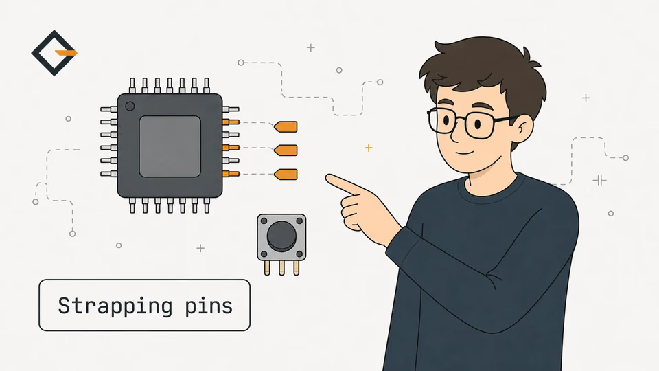
A strapping pin is a GPIO the chip reads at reset to choose how it boots. The ESP32-S3 has four, according to the datasheet's boot configuration chapter: GPIO0 and GPIO46 (boot mode), GPIO45 (VDD_SPI voltage) and GPIO3 (JTAG signal source). The default levels and what each one selects are in ESP32 strapping pins by chip. On this board, GPIO0 is the BOOT button, GPIO3 is pad D2, and GPIO45 and GPIO46 have no D label in Seeed's map.
So the practical answer is short: D2 is the only strapping pin on a pad. The latches sample these pins at reset only, and the datasheet says the pins are then free to be regular I/O, which is why a BOOT button on GPIO0 can double as a user button once the firmware runs. The gizmo-common README uses exactly that: holding BOOT for 10 seconds while the device runs triggers the factory reset.
Is D2 really dangerous, then? With the JTAG eFuses at their default value of 0, the datasheet's JTAG table says GPIO3 is ignored at boot. The risk starts on a chip whose EFUSE_STRAP_JTAG_SEL has been burned: then the level on GPIO3 at reset picks where JTAG comes from. The datasheet also says GPIO3 has no internal pull resistor. I did not test what a stock XIAO does with D2 held low at reset, so I follow the cautious rule the Reolink firmware states in a code comment: stay clear of D2. If you run out of pads, D2 is the last one I would use, as an input with its own resistor.
Other GPIOs are off limits too, but you can't reach them on the XIAO. The ESP-IDF GPIO guide says GPIO26 to GPIO32 are usually used for SPI flash and PSRAM, GPIO33 to GPIO37 as well with octal flash or PSRAM, and GPIO19 and GPIO20 are used by USB-JTAG by default. None of them has a D label here. The strapping pins differ from chip to chip, so don't copy this list to a C3 or a classic ESP32: ESP32 strapping pins by chip compares them.
Which pins can drive a button, a buzzer or a sensor safely?
Use D0, D1 and D3 first. They are plain GPIOs with no default bus function and no boot role, and they are ADC1 and touch capable if you change your mind later. Then pick by what you connect.
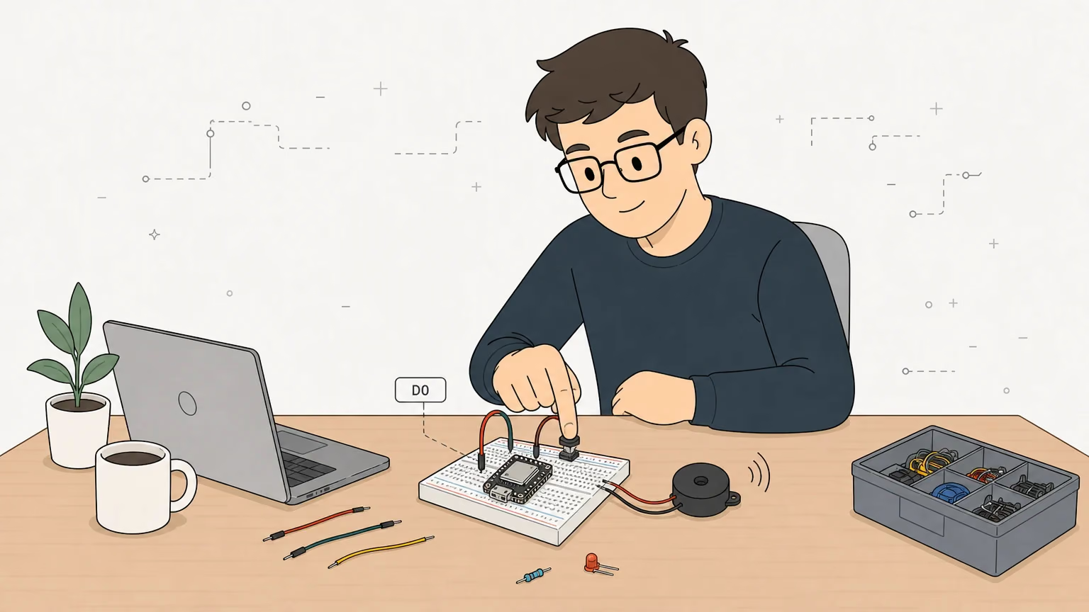
- A button: wire it between the pad and GND, and enable the internal pull-up. The datasheet lists the internal weak pull-up at 45 kΩ typical. The Reolink Switch does this on D0 with
pinMode(config::BUTTON_PIN, INPUT_PULLUP)and reads LOW as pressed, with a 40 ms debounce. - A buzzer: the Reolink Switch drives its buzzer from D1 with plain
digitalWrite, which suits an active buzzer, one that sounds from a DC level. The datasheet's DC table gives 40 mA source and 28 mA sink as typical values at the strongest drive setting, but I did not measure that buzzer's current, and the repository doesn't list a part number. As a rule of thumb, not a datasheet number, anything that pulls more than a few milliamps belongs behind a transistor. - A 5 V part: pads are 3.3 V signals. The datasheet's maximum input high voltage is VDD plus 0.3 V, so 5 V logic does not go straight on a D pad. Power from the 5V pad instead: Seeed's wiki labels it VBUS, and says it carries no voltage when the board runs from a battery. For the regulated 3V3 pad, Seeed's wiki says you can draw 700 mA.
- A sensor on a bus: use D4 and D5 for I2C and D8 to D10 for SPI, as in the previous section.
- An analog input: any of D0 to D5 and D8 to D10, which sit on ADC1 (GPIO1 to GPIO10).
- Serial: D6 and D7 are GPIO43 and GPIO44, the chip's UART0 TX and RX pins. Seeed's wiki says UART0 is not used by default because it carries USB serial communication, and its own
Serial1example uses D6 and D7. Keep them for a GPS, a sensor or a second board talking serial.
The 3D-printed side of this matters too. In the OpenGizmo enclosures the wires leave the board sideways from the edge pads, so the pad you choose also decides where a cable runs. The case design rules are in 3D-printed ESP32 enclosure design rules.
What changes on the XIAO ESP32-S3 Sense and Plus?
The Sense and the Plus use the same chip, but the extras take GPIOs, so the free pins change. My part notes cover only the standard board, so for the other two I rely on what Seeed's wiki says.
| Board | What it adds | Pins it takes or adds |
|---|---|---|
| Standard | Nothing beyond the chip | D0 to D10 on the pads, user LED on GPIO21 |
| Sense | Camera, PDM microphone, SD card slot | Camera GPIO10 to 18, 38 to 40, 47, 48. Microphone GPIO41 and GPIO42 (D12 and D11). SD card CS GPIO21, with SCK, MISO and MOSI shared with D8 to D10 |
| Plus | 16 MB flash, 8 MB PSRAM, more pads | Extra pads D11 to D19 on GPIO38 to 42, 10, 13, 12 and 11 (Seeed's wiki lists D11 and D12 twice with different GPIOs, and its spec table says 18 GPIOs, so check it) |
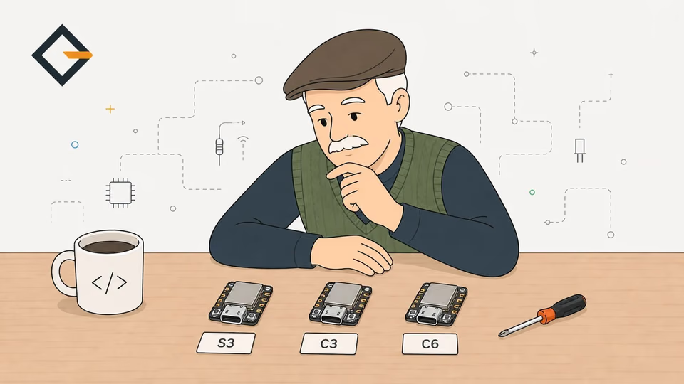
The one that bites is the Sense: its SD card slot shares the SPI pads D8 to D10, so an SPI display on those pads can collide with the card. Seeed's wiki says cutting J3 disconnects the SD card's pull-up resistors, which disables the card and restores normal SPI behavior. The Gizmo Ticker's SPI pads are exactly D8 to D10, and the project's PlatformIO environment targets the standard seeed_xiao_esp32s3 board. If you pick a Sense or a Plus, check the wiki table for your board before you copy any pin. Which XIAO to choose in the first place is the subject of XIAO ESP32-S3 vs C3 vs C6.
How did the Ticker and the Reolink Switch pick their pins?
Both firmwares take pads that sit together near the edge with power, and both leave D2, D6 and D7 empty. The comment in the Reolink Switch's config.cpp says it: the LCD sits on the default I2C pads, the button and the buzzer next to them, "clear of D2 (GPIO3, a boot strapping pin) and of the serial pads D6 and D7".
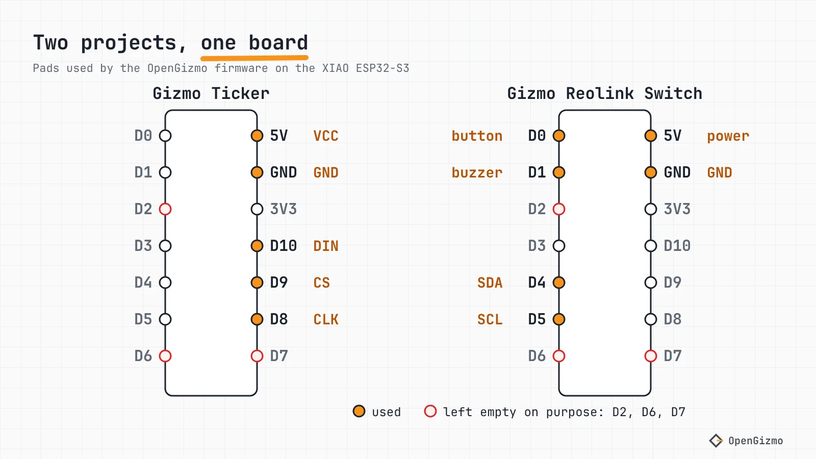
| Project | Part | Pad | GPIO |
|---|---|---|---|
| Gizmo Ticker | MAX7219 DIN | D10 | 9 |
| Gizmo Ticker | MAX7219 CS | D9 | 8 |
| Gizmo Ticker | MAX7219 CLK | D8 | 7 |
| Gizmo Reolink Switch | Button | D0 | 1 |
| Gizmo Reolink Switch | Buzzer | D1 | 2 |
| Gizmo Reolink Switch | LCD SDA | D4 | 5 |
| Gizmo Reolink Switch | LCD SCL | D5 | 6 |
The Ticker's choice has a physical reason. My part notes for the board point out that the right edge reads 5V, GND, 3V3, D10, D9, D8, D7, which is close to the order of a MAX7219 input (VCC, GND, DIN, CS, CLK), so a flat cable runs straight across and the 3V3 wire just stays free. config.h defines the pins only when ARDUINO_XIAO_ESP32S3 is set and stops the build with an #error otherwise, which prevents a silent wrong wiring on another board. The full build is in How to build a crypto ticker with ESP32 and MAX7219.
The Reolink Switch's code uses GPIO numbers instead of D labels, and its comment explains why: so the native tests build on a computer. The button, buzzer and LCD behavior is covered in Control a Reolink NVR with an ESP32.
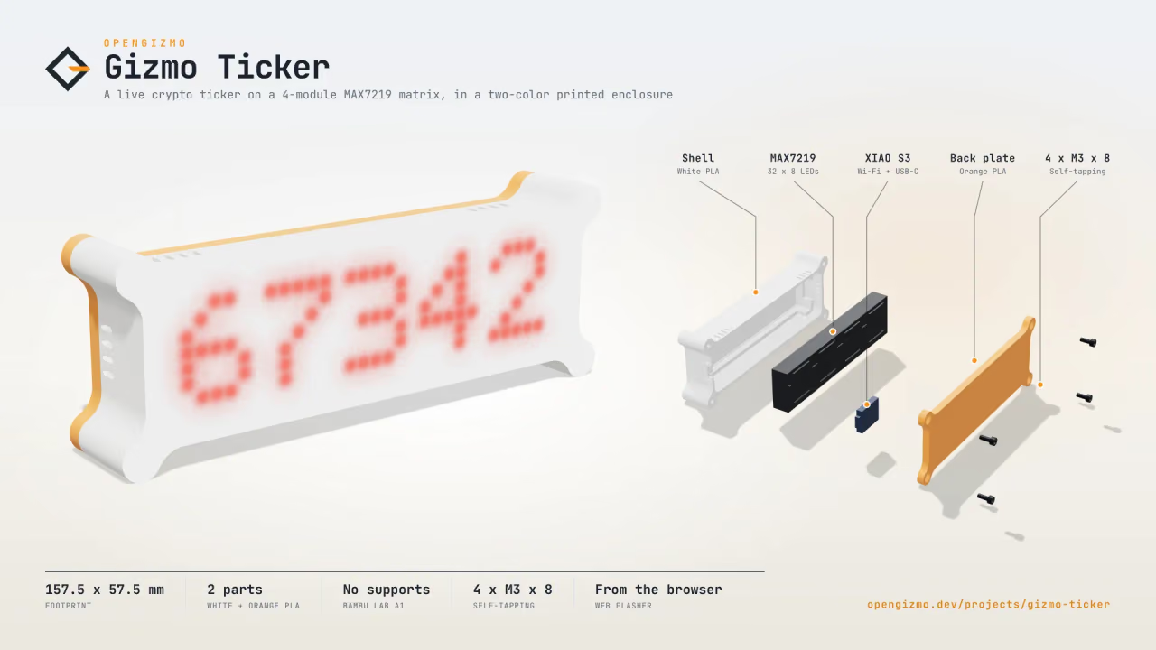
A WiFi-connected crypto display built with an ESP32, a MAX7219 LED matrix, and a Nuxt 4 web app for browser-based setup and configuration.
- Live crypto ticker
- MAX7219 LED matrix
- Web-based setup
One correction while we are here: not every OpenGizmo device uses a XIAO. The Gizmo Camera runs on an AI Thinker ESP32-CAM, which has a completely different pin story, covered in ESP32-CAM GPIO pins: which are really free.
Which XIAO ESP32-S3 pins should you pick first?
Reach for D0, D1 and D3 for buttons, buzzers, LEDs and plain inputs. Use D4 and D5 for I2C and D8 to D10 for SPI, or reroute them in code, since the pads are only defaults. Keep D6 and D7 for serial, and leave D2 (GPIO3) alone, because it is the one strapping pin on a pad. Keep every signal at 3.3 V.
That is what two working firmwares do: the Ticker uses three pads on one edge, the Reolink Switch uses four, and both stay away from D2, D6 and D7. The limits are worth saying plainly. I checked the pin numbers against Seeed's wiki, the datasheet and the code, but I did not scope any pad, test D2 held low at reset, or measure the buzzer's current. Seeed's wiki states no per-pin current limit, and I did not verify revisions of the board. For the chip-level view of the boot pins, read ESP32 strapping pins by chip, and if you are still choosing a board, start with which ESP32 to buy.
Frequently asked questions
Find quick answers to the most common questions about this topic.
The default I2C pins on the XIAO ESP32-S3 are D4 for SDA (GPIO5) and D5 for SCL (GPIO6), according to Seeed Studio's wiki. You can pass other pins to Wire.begin(sda, scl), because the ESP32-S3 can route I2C to most GPIOs, but D4 and D5 are the ones Arduino's Wire uses by default.

Author
Mauro BrambillaReady to build your own gizmo?
Pick an open-source ESP32 project and follow its step-by-step guide, from the parts list and wiring to the firmware and the first boot.