3D-Printed ESP32 Enclosure Design Rules That Fit
How to design a 3D-printed ESP32 enclosure that fits: clearances, board holders, M3 screws, vents, antenna and PLA vs PETG, with real OpenGizmo numbers.
- Author
 Mauro Brambilla
- Published
- Reading time
- 12 min
- Category
- Builds
In short
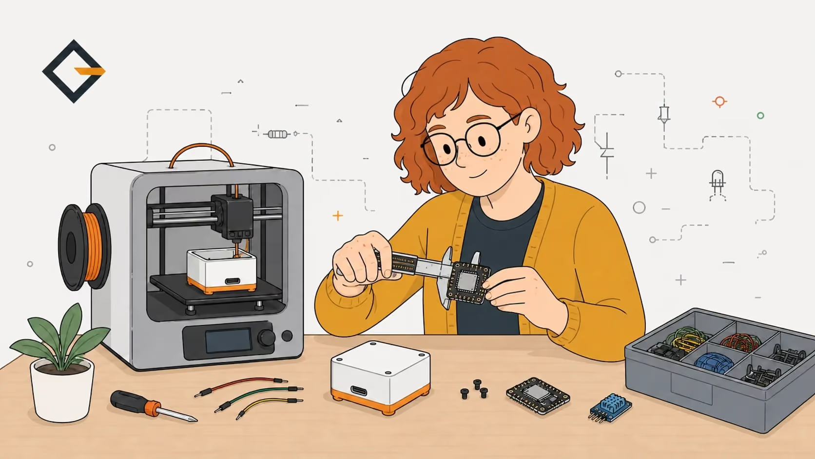
A 3D-printed ESP32 enclosure fits when the pocket has 0.25 mm of clearance per side, the board is held by guides and crush ribs, and an M3 screw cuts its own thread in a 3.0 mm pilot hole. Test small first.
A 3D-printed ESP32 enclosure fits when each pocket is 0.25 mm larger per side than the board, the board is held by guides and crush ribs instead of glue, and M3 screws cut their own thread in a 3.0 mm pilot hole. Print a small fit test first. These are my numbers for the XIAO ESP32-S3.
This guide comes from the real design files of OpenGizmo: my enclosure rules, part notes and test prints. Those notes and the CAD files are not public yet. Every dimension below is a value in a script that builds the model, with its source next to it. Everything was designed for a Bambu Lab A1 with a 0.4 mm nozzle and PLA, so treat the numbers as a starting point for your printer.
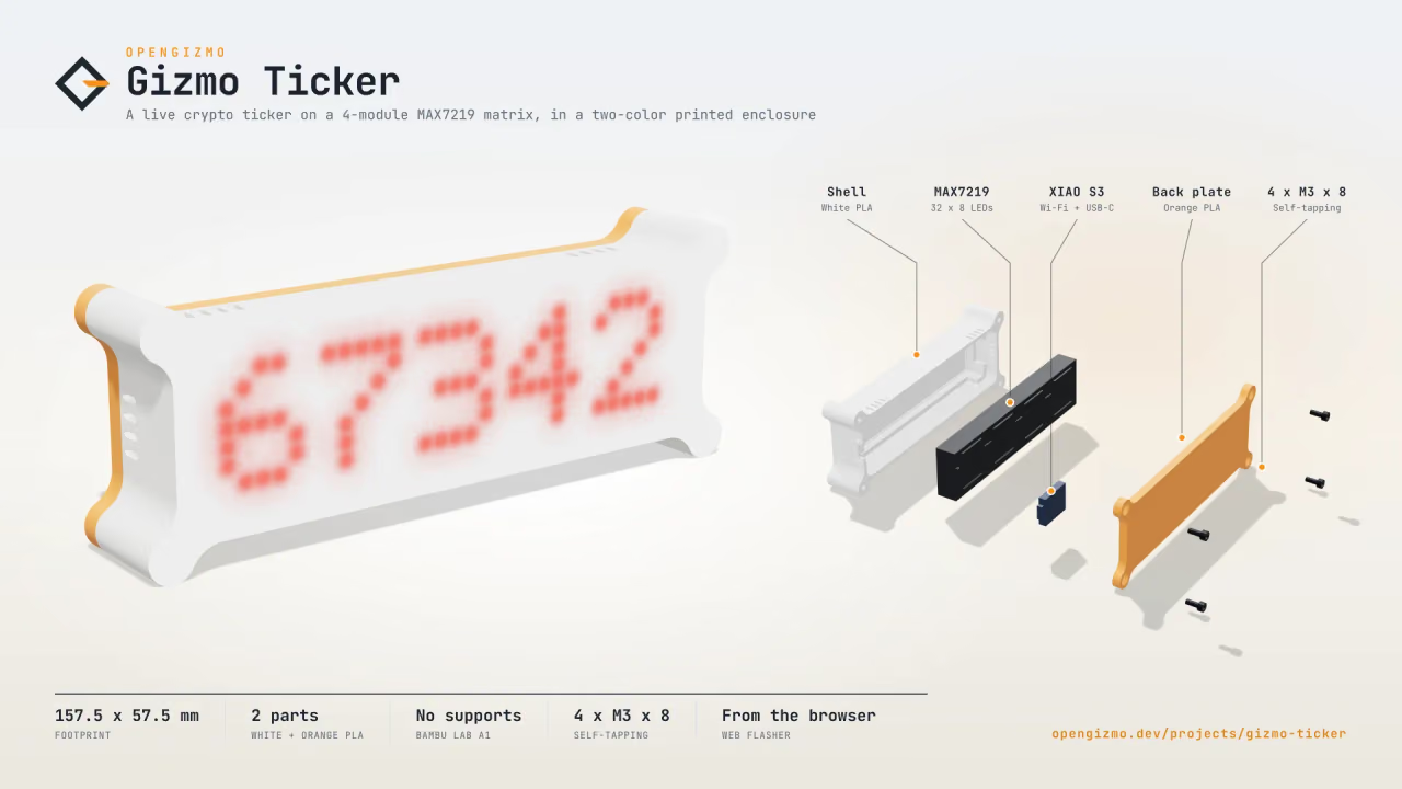
A WiFi-connected crypto display built with an ESP32, a MAX7219 LED matrix, and a Nuxt 4 web app for browser-based setup and configuration.
- Live crypto ticker
- MAX7219 LED matrix
- Web-based setup
What does a good ESP32 enclosure need?
A good enclosure for an ESP32 board does five jobs: it holds the board still, lets the cable plug in, lets heat and radio out, closes with something you can reopen, and prints without supports. A case that fails usually fails one of those jobs, not a millimeter here or there.
- The board cannot move when you push or pull the USB cable
- The USB-C port is reachable with a normal plug, not only a bare cable end
- Warm parts have a way for air to leave, and the antenna sits on plastic
- One kind of screw closes it, and you can open it again
- Every face slopes at 45 degrees or less, so the slicer needs no supports
That last point drives the shape of everything else. OpenGizmo's enclosures are designed in their print orientation, visible faces on the bed, printed in PLA at 0.2 mm layers with 4 walls and no slicer supports. A script (check_overhangs.py) stops the build on any face steeper than 45 degrees that is not on the bed. Where a part would need support, the model has a hidden 45 degree gusset instead.
How much clearance should you leave around the board?
Clearance is the gap you add between a part and the pocket that holds it. Printed plastic never lands exactly on the model, so the right gap depends on how the part should move. These are the values from my printing rules for the A1, per side.
| Type of fit | Clearance per side (mm) | Use it for |
|---|---|---|
| Press fit | 0.1 | A part that should stay put once pushed in |
| Sliding fit | 0.25 | A board or module you slide in and out |
| Loose fit | 0.5 | A part that may rattle a little, such as a button cap |
| Printed hole, extra | 0.2 (0.3 under 4 mm) | Holes come out smaller than modeled |
Here is how that shows up in the Gizmo Ticker. Its 4-in-1 MAX7219 matrix is 132 x 32 mm (measured, because sellers list anything from 128 to 132 mm), so its pocket is 132.5 x 32.5 mm. The matrix test print fit it, according to my part notes for the matrix. The USB-C slot in the end wall is the receptacle (8.94 x 3.26 mm, from the USB Type-C specification) plus 0.3 mm around it, so 9.54 mm wide.
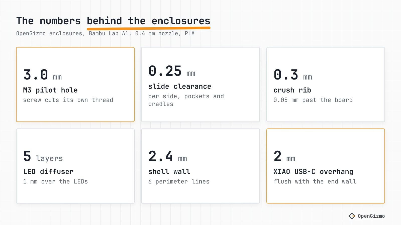
Wall thickness is the other number to settle early. My rule is at least 1.2 mm (three perimeters with a 0.4 mm nozzle) for anything that holds a screw. The OpenGizmo style uses 2.4 mm, six lines, for a stiff shell, and 0.8 mm as the floor for non-structural ribs. The shared values live in one style file that every enclosure script reads.
How do you hold the board so it cannot move?
You hold it by its edges, with features that touch the bare PCB where there are no pins, and you let the plastic take the force of the plug. A XIAO ESP32-S3 is 21 x 17.8 mm, with a USB-C receptacle that sticks out 2 mm past the board end (Seeed's wiki lists the 21 x 17.8 mm size; the 2 mm is measured in the part notes). My part notes for the XIAO turn that into six rules, and they work for most small boards.
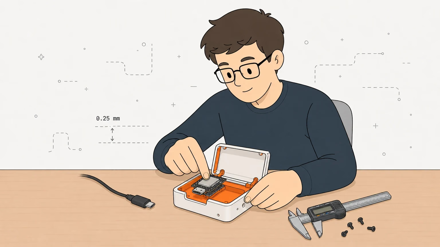
- Put the USB-C face flush with the outside of the wall. The cable's overmold is bigger than the port, so it then seats against the wall, and the hole only needs to clear the receptacle plus 0.3 mm. The PCB end ends up 2 mm inside the outer face.
- Use corner guides with crush ribs. The XIAO has seven pins a side along the middle of its long edges, so the corners are free. Guides there stop sideways play. The ribs stick out 0.3 mm, which is 0.05 mm past the board once you count the 0.25 mm clearance, and they squash as you press the board in. In the notes, a 0.4 mm rib (0.15 mm past the board) was too tight on the XIAO test print.
- Make guides thick enough to survive. 1.2 mm guides broke, so they are 2 mm (five lines), thickened outwards only so the fit does not change. Free-standing 1.2 x 2 mm fingers also broke after a few insertions.
- Add stops at the far end. Two corner Ls joined by a low bar take the plugging force, so it never reaches the solder joints. The cradle is 0.2 mm longer than the board, because with no slack one print did not take the board.
- Clamp the top of the USB-C receptacle. A post of the shell presses on the flat metal top of the receptacle, so plugging a cable cannot lift the board. Never press the corners at the USB end: the R and B buttons sit 0.3 mm from the PCB end.
- Keep the battery pads and the BOOT and RESET buttons in mind. The pads are on the bottom, so keep them clear of anything conductive. The buttons are on top, unreachable once the case is closed, which is why you flash and reset over USB (and why the 10-second BOOT factory reset is out of reach in a closed case, so you forget the Wi-Fi from the web app instead), as the pinout guide and the no serial data troubleshooting post describe.
I did not measure how much force the plug puts on the board. These features come from the notes' own failures (broken guides, a cradle with no slack) and the principle that the cable should push on plastic, not on solder.
Screws, heat-set inserts or snap fits?
Every OpenGizmo enclosure closes with the same screw: an M3 x 8 socket cap (ISO 4762), black, with a 2.5 mm hex key, screwed straight into the print. No inserts, and no snap fits. One screw for every enclosure means one bit and one hole size to remember.
The pilot hole was picked with a screw test I printed: three posts whose holes differ by 0.1 mm. The first round tried 2.8, 2.9 and 3.0 mm on the A1 in PLA, and 3.0 mm is the value that stayed.
| Value | Size (mm) | Where it comes from |
|---|---|---|
| Clearance hole in the plate | 3.5 | M3 clearance 3.2 mm plus 0.3 mm, since small printed holes shrink more |
| Pilot hole in the post | 3.0 | Screw test on the A1, in PLA |
| Lead-in at the top of the hole | 0.4 at 45 degrees | Screw test: the screw starts straight |
| Thread in the post | 6 | Twice the screw diameter |
| Pilot depth | 7 | Bite plus 1 mm, so the tip never bottoms out |
| Post diameter | 7 | Pilot plus 2 mm of wall all around |
| Back plate thickness | 2 | Screw length 8 minus 6 mm of bite |
Two habits keep the thread alive. Stop as soon as the screw is snug: in PLA, one more turn strips it and it does not come back. And name a screw by its hex key, not by what the listing says: 1.5 mm is M2, 2 mm is M2.5 and 2.5 mm is M3. My screw notes record an earlier enclosure that was sized for M2 screws that turned out to be M2.5.
Why no snap fits? Printed parts are weakest between layers, and a thin clip standing upright loads exactly that weakness. My rule is to avoid thin pegs and clips, and the broken fingers above are a small example: the design now holds the PCB end in a notch of the plate rim instead, which is still waiting for its next test print. Heat-set inserts are for parts opened often or under load: the Reolink Switch fit test tries M3 insert holes (ruthex M3 x 5.7, hole sizes 3.9, 4.0 and 4.1 mm) and M2.5 self-tapping holes (2.1, 2.2 and 2.3 mm) for the LCD, and those results are still open.
Where should vents, USB and antenna cutouts go?
Put vents where heat leaves, the USB opening where the plug can seat, and the antenna on plastic with nothing metal near it. A vent is only an opening with a shape the printer can bridge, so the shape matters more than the size.
Vents. The OpenGizmo vent is a slot 1.6 mm wide and 6 mm long (four lines wide), pointed at 45 degrees at both ends so it prints without supports. Four slots make a strip, 4 mm apart, running front to back. In the Ticker they are on the top and the ends, 20 mm in from each end on the top, with one strip over the XIAO and slots low on the ends so air can come in. The ESP32-S3 gets warm, so the notes say not to wrap it in a tight pocket with no air. I did not measure temperatures inside the case.
USB. The Ticker's slot is open towards the back plate, so there is no bridge to print and the flat plate rim closes it. The plug area is sized for a common USB-C overmold of about 12.5 x 7 mm, which the notes mark as "fit test with your cable": measure yours.
Antenna. The XIAO ESP32-S3 has no antenna on the board. It has a U.FL connector, and the flexible antenna in the box connects to it, as Seeed's wiki shows. In the Ticker the antenna, about 37 x 17 mm as measured, is stuck flat on the back plate, with no recess because it is under 1 mm thick, and its stiff cable runs straight along the plate. Ribs crossed by the cable stop below it. For boards with a PCB antenna, Espressif's hardware design guidelines recommend at least 15 mm of clearance in all directions around the antenna in a housing, so check your board's manufacturer before you put anything close. If your device is the ESP32-CAM, the ESP32-CAM-MB guide covers the board and the printed Gizmo Camera enclosure has pinholes for the MB board's IO0 and RST buttons.
PLA, PETG or ASA for electronics?
For a desk gadget in a cool room, PLA is a good choice, and it is what OpenGizmo uses. The catch is heat: my rule is that PLA softens at around 55 °C, so keep it away from regulators, chargers, batteries, direct sun and a car in summer. That 55 °C is my own rule of thumb, not a measurement of your spool, so check your filament's datasheet.
| Material | Good for | Watch out for |
|---|---|---|
| PLA | Cool indoor boxes, fit prototypes, easy printing | Brittle, softens around 55 °C |
| PETG | Cool indoor low-voltage enclosures, a step up in heat tolerance | I have not printed these enclosures in PETG |
| ASA | Sun, hotter places, outdoor use; Prusa guides give up to 93 °C as a material guidance value | Warps and cracks without an enclosed printer |
| ABS | Only with a validated process | Warps, same as ASA |
The comparison follows a vendor guide to electronics enclosure filaments: PETG for most cool indoor low-voltage boxes, ASA for sun or heat, PLA for fit prototypes and low-risk indoor boxes. It also warns that none of these filaments is flame-rated by default, so a box on mains voltage needs its own testing. The Seeed wiki's spec table lists a working temperature of -20 to 65 °C and does not say which XIAO model it applies to, so I would not put a PLA case in a place that gets that hot. Everything here concerns low-voltage USB gadgets.
I have not printed these enclosures in PETG or ASA, so my own numbers are for PLA only. If you switch, re-run the screw test: the pilot hole depends on the printer and the filament.
How do you check the fit before printing it all?
Print small, ahead of the full parts. A fit test is a piece cut from the real design that contains only the features that can go wrong, so a bad value costs a few grams instead of a few hours. My enclosure guidelines put it in one line: print from small to large.
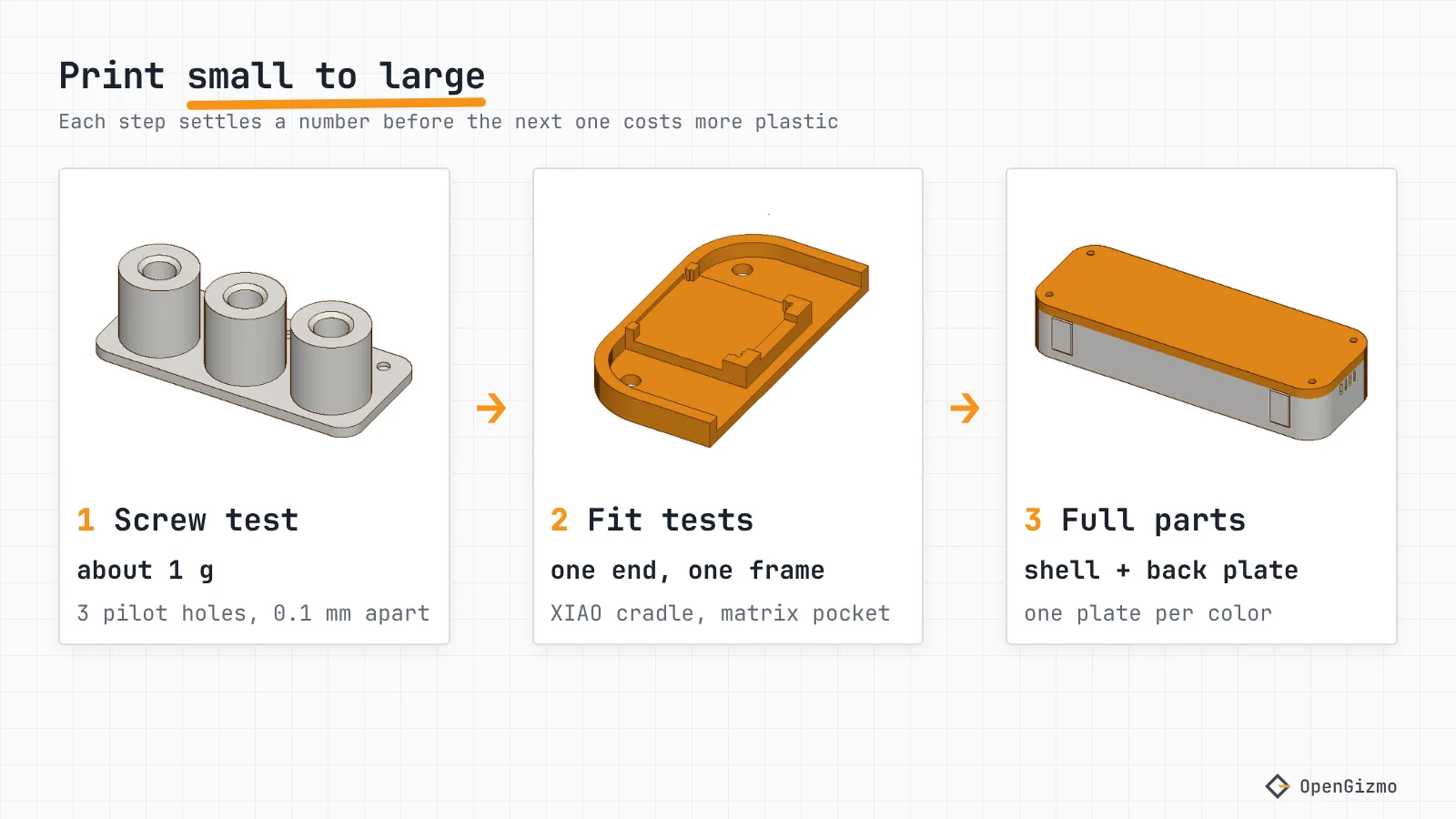
- The screw test (about 1 g). Three posts as thin as the real ones, each with a different pilot hole, and a tab as thick as the back plate. Screw the M3 x 8 through the tab into each post and note which one grips. Do this when the printer, the filament or the screw is new.
- A fit test of one end. For the Ticker, the fit test I printed has the input end of the enclosure, a XIAO platform with the USB-C notch, a matrix frame and a diffuser frame, each as a 3MF plate. The Reolink Switch has an LCD fit test and a block with insert holes, screw holes, a buzzer pocket and a XIAO cradle.
- The full parts. One plate per color: the white shell and the orange back plate.
A separate diffuser test settled the front of the Ticker: a frame with four strips closed by 2, 3, 4 and 5 layers, laid on the running module. The enclosure uses 5 layers (1 mm), picked on that test over 2 to 5 layers, so the LEDs read as soft pixels. That is a choice for this display and filament, not a universal number.
Check the numbers before you look at pictures. The build script prints the sizes, gaps and overlaps, and stops if a sketch is under-constrained, a part is not one solid or two parts overlap. A model that builds proves the geometry, not the fit, which is why the print tests exist.
What do the OpenGizmo enclosures do differently?
They share a look and a small set of rules, so every gizmo on a desk reads as one family. The rules in my enclosure guidelines are short: a frame of constant width around whatever is on the front, square edges with a rounded outline, a white body and an orange back, with the back plate's rim reaching 3 mm into the shell so it reads as a thick band of color. Anything you look at or touch goes on the front. Screws, ports and cables go on the back.
The Gizmo Ticker is the most complete example, at 153.6 x 53.6 mm seen from the front. Its frame is 11.05 mm wide, wider than the standard 6 mm, so the whole 7 mm screw posts fit in the corners, and the module slides in from the back. A hollow frame band saves filament, and grip notches let you pinch the module out by its PCB edges instead of pulling its wires. The build behind it is in the crypto ticker guide.
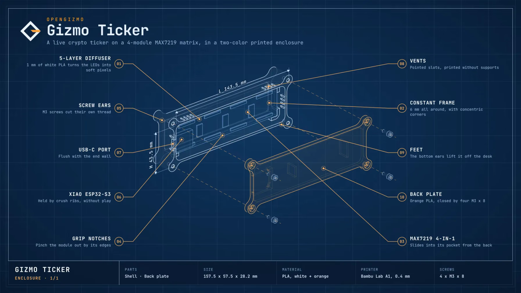
The Gizmo Camera enclosure follows the same rules around an ESP32-CAM on its MB board, on a 57.4 x 44.6 mm footprint, with a flared lens window, vents, pinholes for the MB board's buttons and a ball socket for the stand. The Gizmo Camera page shows its blueprint.
For the Gizmo Reolink Switch there is no finished enclosure yet, only fit tests for the LCD and the parts, and its build post is about the firmware.
What is verified, and what is still open?
The rules above come from my design scripts and notes: 0.25 mm of sliding clearance, a 3.0 mm pilot hole for an M3 x 8 screw in PLA on the A1, crush ribs of 0.3 mm, a 5-layer diffuser, 2.4 mm walls, and one screw for every case. The pilot hole, the diffuser and the matrix pocket were settled with print tests.
The limits are in the docs too. They list two items still to confirm with the first full enclosure: sharp bed edges with no chamfer (the slicer's elephant foot compensation should do it) and how the pointed vent slots print in a wall. The XIAO notes also list the rim notch, the flush USB-C and the joined far stops as the next test print, and the U.FL position was measured from a photo. I did not test other printers, filaments or boards, and the Reolink Switch enclosure is not designed yet.
If you want the device these rules were made for, start with the Gizmo Ticker project page or the OpenGizmo overview. For your own case, print the screw test first. It takes about a gram of PLA and saves you a stripped thread.
Frequently asked questions
Find quick answers to the most common questions about this topic.
As a starting point on a 0.4 mm nozzle, leave 0.25 mm per side for a board that slides in and out, 0.1 mm for a press fit and 0.5 mm for a loose fit. OpenGizmo's enclosures use 0.25 mm around the XIAO ESP32-S3 and the LED matrix, then adjust with a small fit test.

Author
Mauro BrambillaReady to build your own gizmo?
Pick an open-source ESP32 project and follow its step-by-step guide, from the parts list and wiring to the firmware and the first boot.