ESP32-CAM-MB: Program the ESP32-CAM Over USB
How to program an ESP32-CAM with the ESP32-CAM-MB USB board: what it contains, the IO0 and RST button sequence, flashing from Chrome, and what fails.
- Author
 Mauro Brambilla
- Published
- Reading time
- 9 min
- Category
- Guides
In short
The ESP32-CAM-MB is a micro-USB carrier with a CH340 serial chip, IO0 and RST buttons. Usually you just click upload; if the connection fails, hold IO0, tap RST, release IO0.
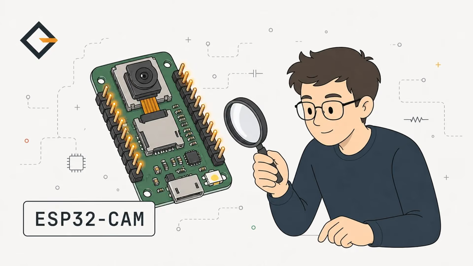
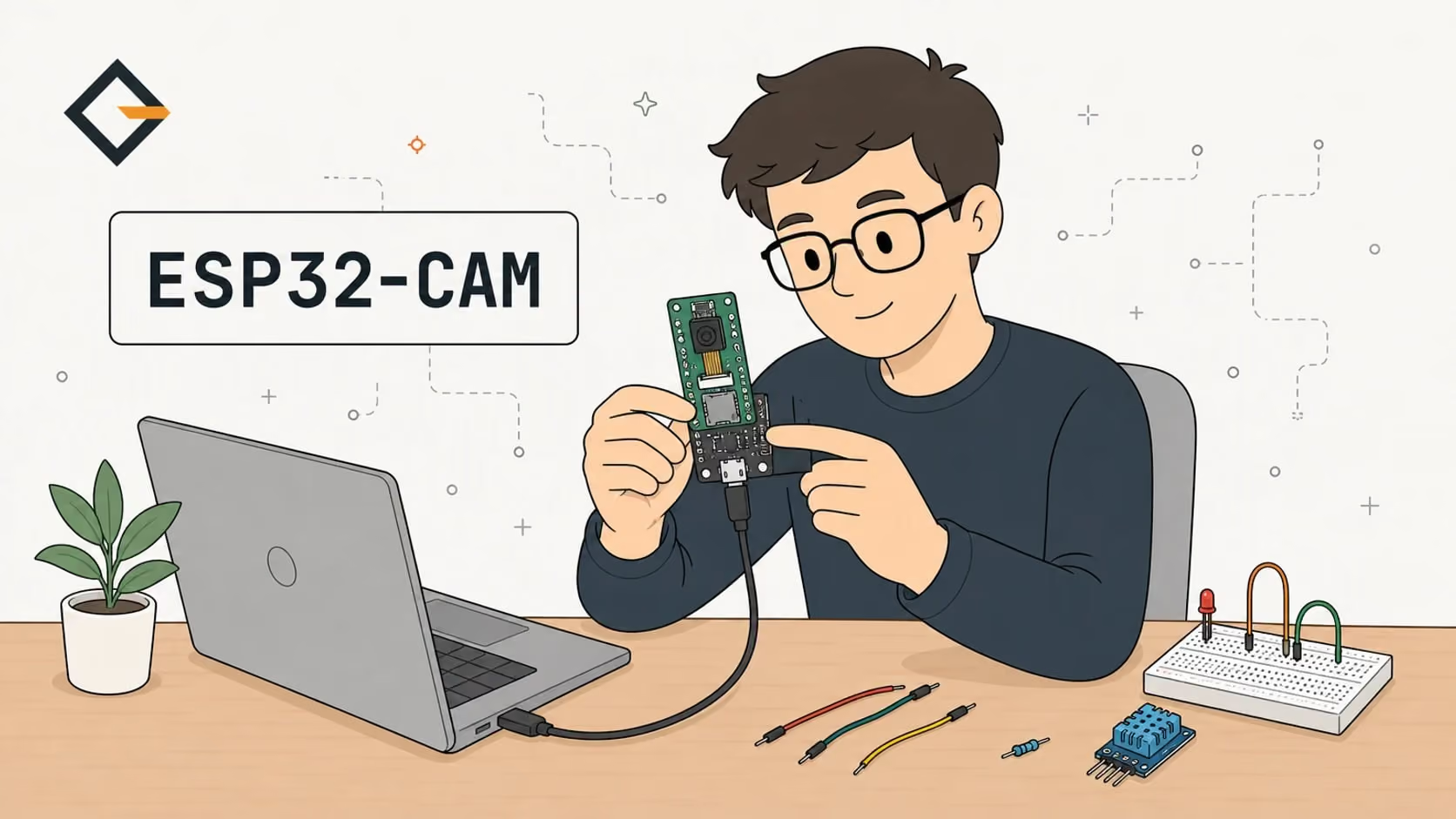
The ESP32-CAM-MB is a USB carrier board for the AI Thinker ESP32-CAM, which has no USB port of its own. It adds a micro-USB socket, a CH340 USB-to-serial chip and two buttons, IO0 and RST. Usually you just click upload. If the connection fails, hold IO0, tap RST, then release IO0.
Do you have an ESP32-CAM that refuses to take a program, or a board you want to flash without installing an IDE? This guide covers what the MB board does and doesn't do, the manual button sequence, how to flash from Chrome, and what happens to IO0 afterwards. The steps come from the Gizmo Camera README, the firmware's platformio.ini, and the manufacturer docs linked inline. I have not run these steps on hardware for this guide, and where the sources disagree I say so.
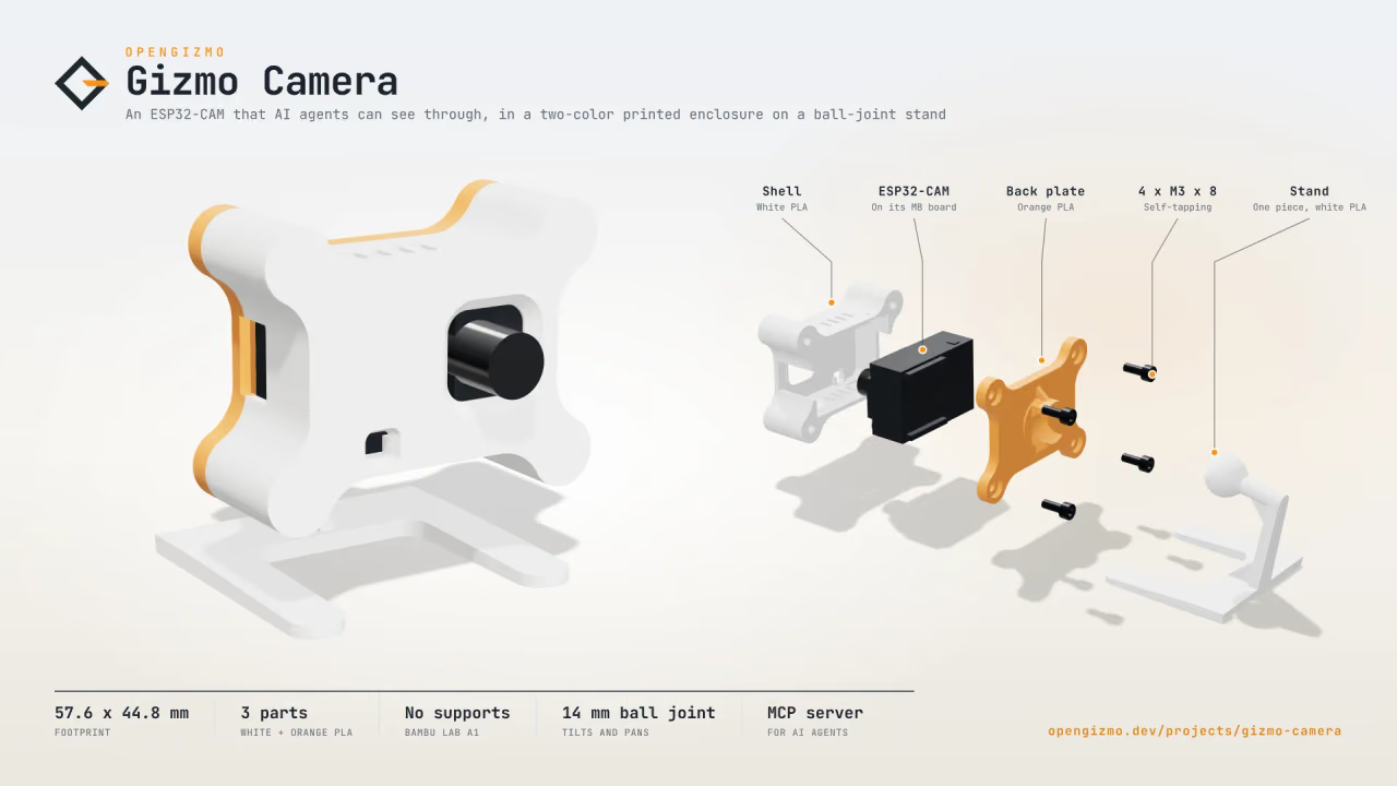
An ESP32-CAM Wi-Fi camera that takes a JPEG snapshot on every request, with a web app to set it up from your phone and an MCP server for AI agents.
- JPEG snapshots up to 1600 × 1200
- Simple HTTP API
- MCP server for AI agents
What is the ESP32-CAM-MB board and why do you need it?
The ESP32-CAM-MB is a USB programmer board that the ESP32-CAM sits on. The ESP32-CAM itself has no USB connector, and per Random Nerd Tutorials' pinout guide it has no built-in programmer: its serial pins are GPIO1 (TX) and GPIO3 (RX), and a bare board is normally programmed through an external adapter such as an FTDI. The MB board is that adapter, shaped to fit the module.
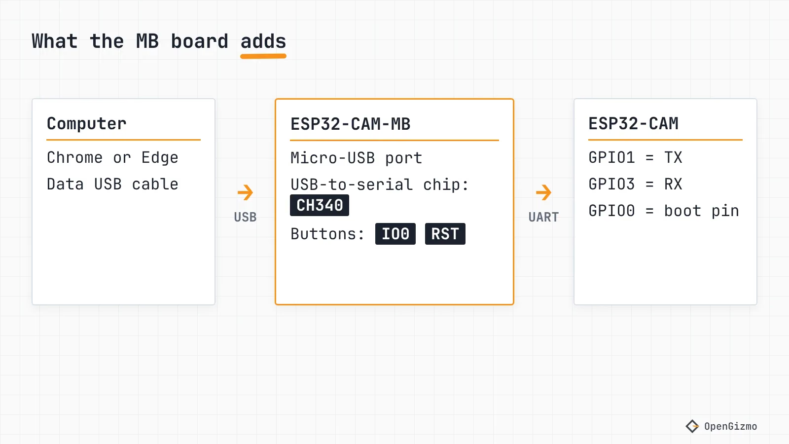
What the board contains, according to Random Nerd Tutorials' ESP32-CAM-MB walkthrough (read in November 2026):
| Part | What it does |
|---|---|
| Micro-USB socket | Connects to your computer: power and data in one cable |
| CH340 USB-to-serial chip | Turns USB into the UART the ESP32 bootloader speaks |
| IO0 (BOOT) button | Pulls GPIO0 low, which selects download mode at reset |
| RST (RESET) button | Resets the ESP32 |
What it does not contain: a camera, a battery, or anything that changes the module's pins. The firmware sees the same ESP32-CAM, so the pin rules in which ESP32-CAM GPIO pins are really free still apply.
Which USB chip is on your board?
Most MB boards use a CH340, but you should check, because the driver depends on it. Random Nerd Tutorials calls the chip CH340C in the text and CH340G in the captions, and the Arduino forum thread describes a CH340G board. In a Home Assistant community thread one user compares a CP2102 board and a CH340C board, so both exist. Three ways to identify yours:
- Read the chip. Look for the chip near the micro-USB socket: it is usually marked CH340C, CH340G or similar.
- Windows. Open Device Manager, then Ports, with the board plugged in. A CH340 typically appears as "USB-SERIAL CH340 (COMx)" once its driver is installed.
- Linux. Run
lsusband look for vendor ID1a86. The Linux kernel's ch341 serial driver lists1a86:7523among the devices it binds, and a CH340 typically reports that ID. Linux includes the driver, so no install is needed.
If no new port appears at all, the cable is the first suspect: see the data-cable check in the failed-to-connect guide.
How do you seat the ESP32-CAM on the MB board?
Seating means pushing the module's two pin rows fully into the sockets of the MB board. The point is electrical: the serial lines, 5 V and GND all pass through those pins, so a half-seated module can look powered and still never answer the programmer. The Gizmo Camera troubleshooting notes say the same thing: check that the ESP32-CAM sits fully in its MB board before anything else.
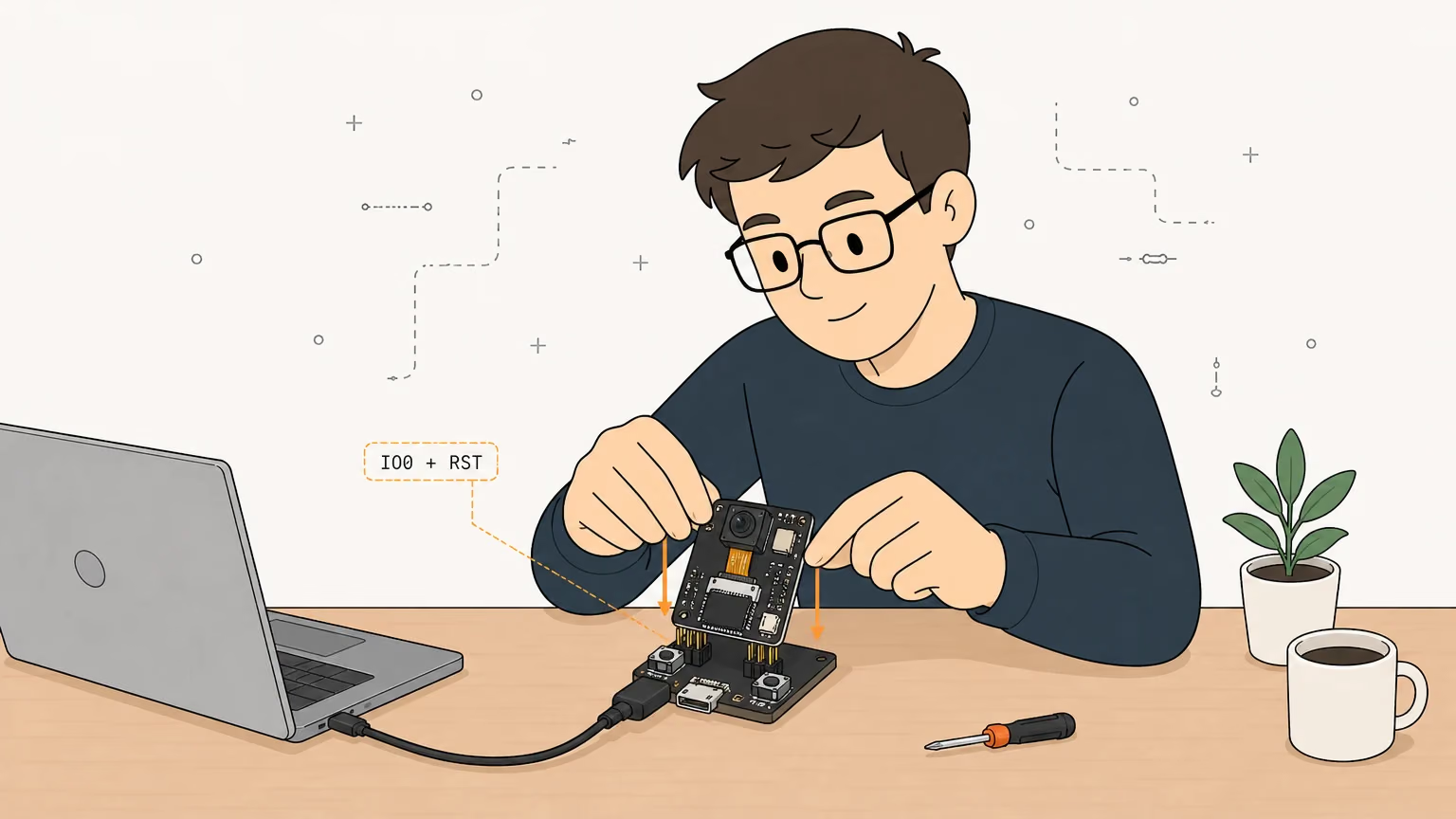
- Unplug the USB cable first.
- Align the pin rows with the sockets and press the module down evenly. Do not force it.
- Check that the camera ribbon cable is fully inserted and its latch is closed. This is a separate fault: the Gizmo Camera web app shows "Camera not found" when the sensor did not start.
- Plug the USB cable into the computer, using a data cable. Many cables only charge.
In the printed Gizmo Camera enclosure you reach IO0 and RST with a paperclip through the pinholes in the long sides, one button on each side, per the project README.
Do you need to hold IO0? The upload sequence
Most of the time, no. Download mode is the state in which the ESP32's ROM bootloader waits for a flasher. Espressif's esptool documentation says tools enter it by asserting the DTR and RTS lines of the USB-to-serial chip, wired to GPIO0 and EN. Random Nerd Tutorials says that with the MB board you can select AI-Thinker ESP32-CAM, pick the port and click Upload, and that the buttons are only for when it fails. I could not find the MB board's schematic, so I cannot confirm how it wires those lines: treat "it usually resets itself" as reported, not guaranteed.
When the upload fails, do it by hand. This is the sequence in the Gizmo Camera README:
- Hold the IO0 button.
- While holding it, press and release RST.
- Release IO0.
- Start the flash again. You should see the connection succeed within a few seconds.
- When the upload completes, press RST once so the new firmware starts.
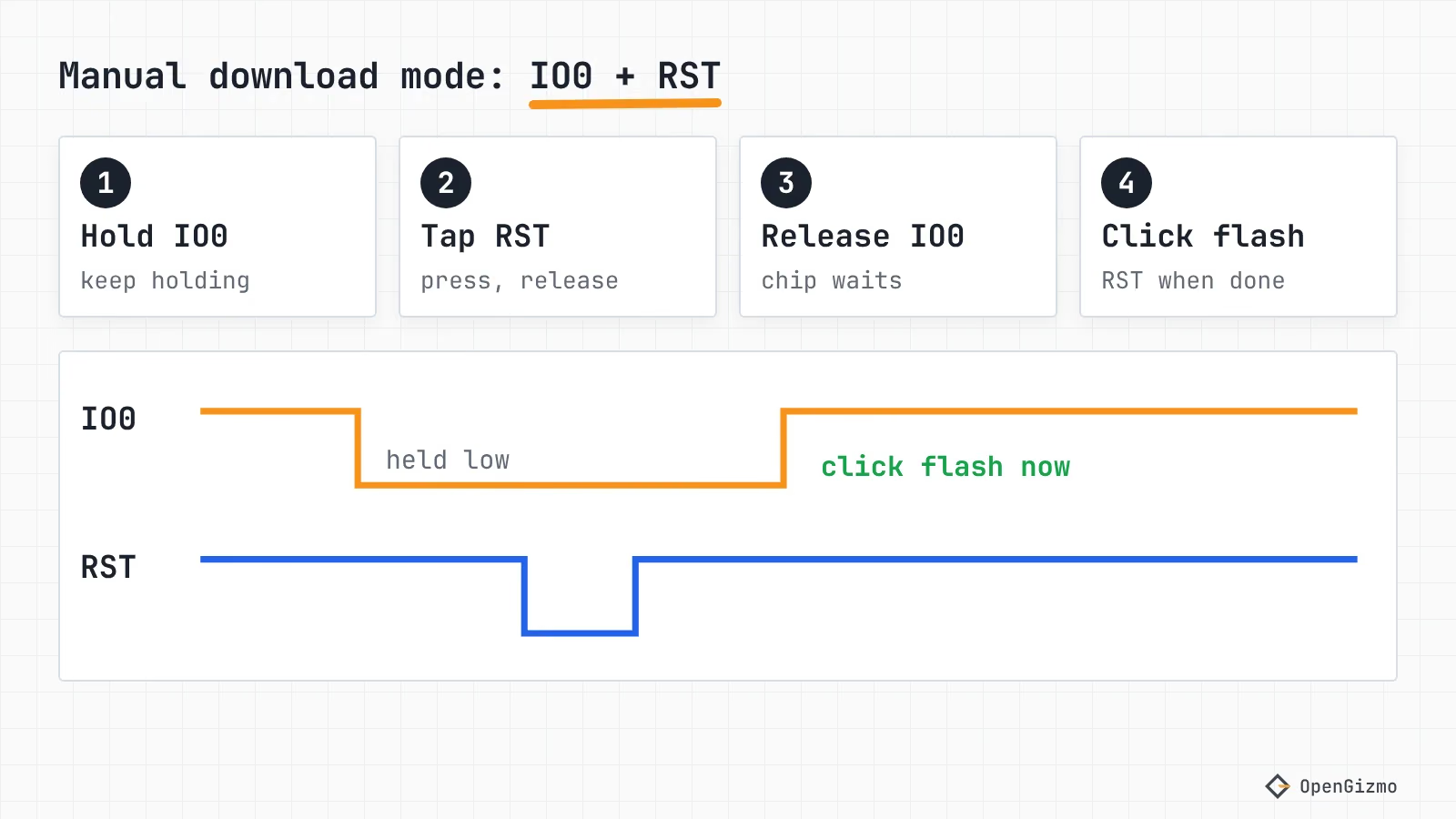
The reason it works: Espressif says the ESP32 enters the serial bootloader when GPIO0 is held low on reset. A pull-up keeps the pin high when nobody presses the button: Random Nerd Tutorials' pinout guide says 10 kΩ on the board, and Espressif's boot mode page says the chip's own internal resistor on GPIO0 is 45 kΩ. Either way, leaving the button alone lets the program run. IO0 only matters at the moment of reset.
Two variations show up in the sources, so try them one at a time if the first does not work:
- Hold IO0 while you plug the board into USB, release it after it connects, then upload. This is "option 1" in the Random Nerd Tutorials article.
- Tap the small reset button on the ESP32-CAM itself, not the one on the MB board. The Random Nerd Tutorials author recommends this in a comment: when the dots appear in the upload log, hold the programmer's IO0 and press the camera's own reset. The Gizmo Camera README uses the MB board's RST, and I haven't checked which behaves better on every revision.
How do you flash from Chrome with no Arduino IDE?
You can flash the Gizmo Camera firmware from the browser. The project page has a flashing card built on esptool-js that uses Web Serial, the browser API for serial ports, so it works in Chrome or Edge on a desktop, over HTTPS. The same Web Serial mechanics, as used by ESP Web Tools on the other OpenGizmo projects, are explained in ESP Web Tools: flash an ESP32 from your browser.
- Seat the ESP32-CAM on the MB board and plug it into the computer.
- Open the Gizmo Camera page in Chrome or Edge and scroll to the firmware card.
- Press Flash firmware and choose the board's serial port in the browser's picker. You should see the card report the chip it found.
- If it cannot connect, use the IO0 and RST sequence above, then press the button again.
- When the card says it is done, press RST on the MB board. The README asks for this step even though the flasher sends its own reset.
- Join the
Gizmo-CameraWi-Fi network from your phone and pick your network, as the project page describes.
What the flasher writes is listed in the manifest on the CDN (version v1.0.0, fetched November 14, 2026). It is an ESP32 build with four parts:
| Part | Offset (decimal) | Offset (hex) |
|---|---|---|
| release-bootloader.bin | 4096 | 0x1000 |
| release-partitions.bin | 32768 | 0x8000 |
| release-boot_app0.bin | 57344 | 0xE000 |
| release-firmware.bin | 65536 | 0x10000 |
The card connects at 115200 baud and does not erase the whole chip, so settings saved on the board, such as your Wi-Fi network, survive an update. That detail is in the flasher component of this site's source (FlashFirmware.vue), which sets eraseAll: false.
Prefer Arduino IDE or PlatformIO?
Both work with the MB board. In Arduino IDE, Random Nerd Tutorials picks AI-Thinker ESP32-CAM under Tools, Board and the serial port under Tools, Port. In PlatformIO, the Gizmo Camera firmware uses the board esp32cam with platform = espressif32 @ 8.0.0 in platformio.ini (in the Gizmo Camera repository), and uploads with:
cd microcontrollerpio run --target uploadThe same file turns the serial log off in the released firmware, so the serial monitor stays silent after a normal flash. That is by design: flash the debug profile (pio run -e debug --target upload, then pio device monitor) when you want logs. If you cannot decide between the two tools, Arduino IDE vs PlatformIO for ESP32 compares them.
Why does flashing fail on this board?
Change one thing at a time and read the message first. The error texts below come from Espressif's esptool troubleshooting page, and the board-specific causes from the Gizmo Camera README and the threads linked above.
| What you see | Likely cause | Try this |
|---|---|---|
| No new serial port | Charge-only cable or missing driver | Use a data cable, install the CH340 or CP2102 driver, then replug |
| No serial data received | No reply from the bootloader: wiring, or the chip never entered download mode | Check the seating, then hold IO0 and tap RST |
| Wrong boot mode detected (0xXX) | Communication works but the automatic reset did not enter download mode | Do the IO0 and RST sequence by hand |
| Invalid head of packet (0xXX) | Poor cable or a brownout during flashing | Change the cable or port, then retry at a lower baud rate |
| Upload works, nothing runs | Still in the bootloader, or IO0 held at reset | Release IO0, then press RST |
| Board restarts when the flash LED or Wi-Fi starts | Weak USB port or cable | Use a powered port or a 5 V supply |
Some boards simply behave differently. In the Home Assistant thread above, users reported pressing a button during the upload, unplugging the board and holding RST and IO0 while plugging it in, or fixing a CP2102 board by updating its driver; one user's CH340C board still failed after several tries. None of these is a guaranteed cure, so work from the table down.
If the board resets during flashing, power is the likely culprit. The esptool troubleshooting page says the chip's 3.3 V supply must handle up to 70 mA continuous and 200 to 300 mA peaks, and the Gizmo Camera README names the flash LED and Wi-Fi setup as the moments when a weak USB port or thin cable browns out. The brownout detector guide walks through the power path. The broader checklist for the generic error is in Failed to Connect to ESP32: No Serial Data Received.
What happens to IO0 after flashing?
After flashing, IO0 does nothing as long as you leave it alone. GPIO0 is the boot-mode pin, and it is also the camera's clock: the Gizmo Camera camera_pins.h assigns it to XCLK_GPIO_NUM, and the README notes that this is why the firmware never reads it as a button and has no BOOT-button factory reset. To start Wi-Fi setup again, forget the network from the web app, or move the camera out of range of the saved network and it opens its setup hotspot again.
Two practical consequences:
- Don't hold IO0 at reset unless you want download mode. A reset with GPIO0 low starts the bootloader, not your program.
- Bare ESP32-CAM with an FTDI adapter: the sequence is different. You connect GPIO0 to GND to flash, then remove the wire, per Random Nerd Tutorials. The MB board replaces that jumper with the button.
Once the camera runs, the next step is using it: one HTTP request returns a JPEG, and the same camera can be an MCP server for Claude Code.
What to remember
The ESP32-CAM-MB is a micro-USB carrier with a CH340-class serial chip and two buttons, and it turns the USB-less ESP32-CAM into a board you can flash like any dev board. Normally you click upload; when the connection fails, hold IO0, tap RST, release IO0, flash, then press RST once more. The Gizmo Camera flow, with the sequence, the offsets and the manifest, was read from the repository and the live manifest, not measured on a bench of boards.
What I did not verify: the MB board's schematic and whether its reset circuit differs between revisions, the CH340C and CH340G split across sellers, and the behavior of other browsers than Chrome. Keep a data cable and a decent USB port for the camera, because power is the most common reason it misbehaves after it works. To go on, read the snapshot URL guide or What is OpenGizmo? for the other projects.
Frequently asked questions
Find quick answers to the most common questions about this topic.
Usually not. Random Nerd Tutorials says you can select the AI-Thinker ESP32-CAM board and click Upload, and the buttons are only needed when the upload fails. If it does, hold IO0, press and release RST, then release IO0 and start the upload again.

Author
Mauro BrambillaReady to build your own gizmo?
Pick an open-source ESP32 project and follow its step-by-step guide, from the parts list and wiring to the firmware and the first boot.