ESP32 Partition Table Explained: Flash Layout and OTA
What the ESP32 partition table is, how the partitions.csv columns work, the Arduino-ESP32 schemes with sizes, flash offsets by chip, and what N16R8 means.
- Author
 Mauro Brambilla
- Published
- Reading time
- 10 min
- Category
- Guides
In short
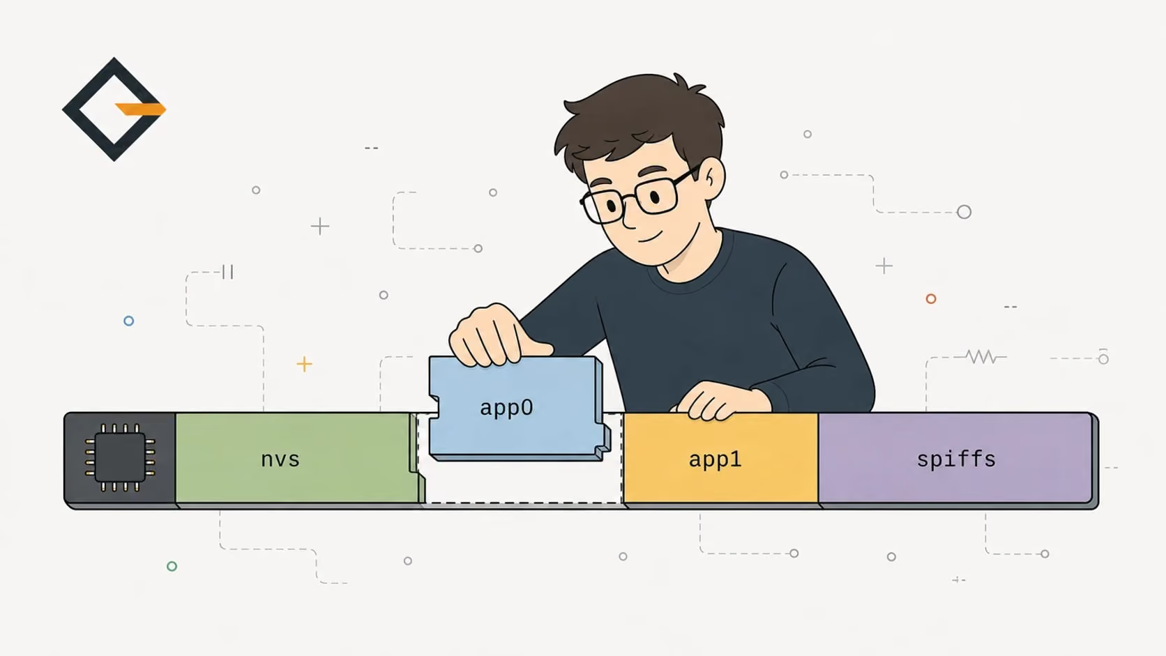
The ESP32 partition table sits at 0x8000 and splits the flash into nvs, otadata, app and filesystem partitions. OpenGizmo's huge_app.csv gives one 3 MB app slot and no OTA.
The ESP32 partition table is a small map stored in flash at offset 0x8000 that tells the bootloader where the app, the settings storage (nvs), the OTA data and the filesystem live. You choose it with a partitions.csv file, or with a built-in scheme such as default.csv or huge_app.csv. If the table runs past the real flash size, Espressif's esptool documentation warns the chip will not work correctly.
This guide reads that map the way the chip does: the CSV columns, the Arduino-ESP32 schemes with their sizes in KB, why the bootloader offset differs between chips, and what N16R8 on a module name means for your layout. The real example is the Gizmo Ticker: I decoded the release-partitions.bin that its flasher writes, and checked it against Espressif's documentation and the Arduino-ESP32 CSV files.
What is the ESP32 partition table?
A partition table divides the external flash chip into named regions with a type, an offset and a size. Espressif's partition table guide says it is flashed at 0x8000 by default, occupies one 4 KB sector, and is 0xC00 bytes long because it allows at most 95 entries, followed by an MD5 checksum the bootloader uses to check its integrity.
The bootloader is the first program that runs from flash. ESP-IDF's bootloader page lists its job: select the application partition to boot, based on the partition table and ota_data if there is one, load the image into RAM and hand over control. So the table is not a setting inside your app. It is a file in flash that exists before your code does.
A typical table holds four kinds of partitions:
- nvs: key-value storage for settings and Wi-Fi data, used by the Preferences library
- otadata: records which OTA app slot to boot, 0x2000 bytes
- app slots (factory, ota_0, ota_1): the firmware images
- data partitions such as spiffs or coredump: a filesystem, crash dumps, or your own bytes
What does a partitions.csv file look like?
The CSV has six columns: name, type, subtype, offset, size and flags. Whitespace is ignored, lines starting with # are comments, and sizes can be hex, decimal or use K and M. A name is at most 16 bytes including the terminator. Here is the real table of every OpenGizmo firmware, from the Arduino-ESP32 core's huge_app.csv as read on November 14, 2026 (its comment line with the column names is left out here):
nvs,      data, nvs,     0x9000,  0x5000,
otadata,  data, ota,     0xe000,  0x2000,
app0,     app,  ota_0,   0x10000, 0x300000,
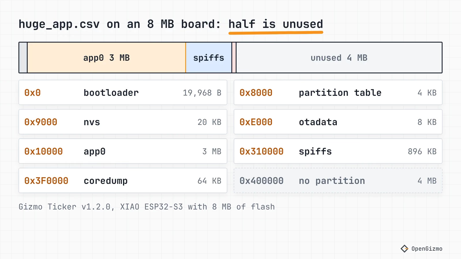
spiffs,   data, spiffs,  0x310000,0xE0000,
coredump, data, coredump,0x3F0000,0x10000,Three rules explain most of the numbers, all from the ESP-IDF guide. Offsets are multiples of 4 KB (0x1000), the flash sector size. An app partition must start at a multiple of 64 KB (0x10000), which is why the first app sits at 0x10000 and the 0x9000 to 0xFFFF area before it holds only small data partitions. And if you leave an offset blank, the partition starts right after the previous one, with app partitions aligned for you.
Type and subtype are what the bootloader and the libraries look for, not the name. Per the same guide, the default nvs partition is the one with type data and subtype nvs, and otadata has subtype ota. The binary table the flasher writes stores them as numbers. I decoded the shipped file with a few lines of Python: nvs is data/0x02, otadata is data/0x00, app0 is app/0x10 (ota_0), spiffs is data/0x82 and coredump is data/0x03.
Which partition table do the OpenGizmo firmwares use?
All three set board_build.partitions = huge_app.csv in platformio.ini, for example in the Ticker's file, with the comment "One 3 MB app slot (no wireless updates), the same in every OpenGizmo firmware". The release-partitions.bin files of the Ticker v1.2.0, the Reolink Switch v1.2.0 and the Camera v1.0.0, as served from the CDN on November 14, 2026, are byte-identical (3,072 bytes), and they decode to exactly the CSV above.
What does that mean for the hardware?
- One app slot, no OTA. There is a single
ota_0slot of 3 MB (3,072 KB) and no second one, so a new image has nowhere to be written while the old one runs. The OTA methods comparison explains why that rules out Wi-Fi updates and compares the slot sizes against the real app. - Room to grow. The Ticker v1.2.0 app is 1,796,736 bytes, about 57% of the slot. The Reolink Switch app is 1,778,336 bytes and the Camera app 1,722,192 bytes, taken from the sizes of the release files.
- Settings are safe. The Preferences library stores data in the NVS partition, and the Ticker's and the Reolink Switch's
storage.cppboth use Preferences. The flasher writes the bootloader, table,boot_app0and app, none of which overlaps 0x9000 to 0xDFFF, as the browser flashing guide describes. - An unused filesystem. The 896 KB
spiffspartition is declared, but searching themicrocontroller/sources of all three firmwares forLittleFS,SPIFFSandspiffsfinds nothing. The sharedgizmo-commonlibrary is not covered by that search. The 64 KBcoredumppartition is where ESP-IDF's core dump feature writes crash data, and whether these firmwares enable it is not something I checked.
One more detail is easy to miss. The XIAO ESP32-S3 has 8 MB of flash (the Plus model has 16 MB) according to Seeed's wiki, and PlatformIO's own board file for it points to default_8MB.csv. The OpenGizmo override to huge_app.csv ends at 0x400000, so the upper 4 MB of that flash has no partition at all. It costs nothing to leave it empty, and the firmware's own platformio.ini comment says the same table is used in every OpenGizmo firmware, including the 4 MB ESP32-CAM.
What are the default Arduino-ESP32 partition schemes?
The Arduino-ESP32 core ships dozens of ready-made tables in its tools/partitions folder: the folder held more than 50 files on November 14, 2026. In Arduino IDE they are the Tools, Partition Scheme menu, and in PlatformIO you name the file in board_build.partitions, as the PlatformIO Espressif 32 docs show. These are the ones you meet most:
| Scheme file | Flash needed (MB) | App slots | Each app slot (KB) | Filesystem (KB) |
|---|---|---|---|---|
| default.csv | 4 | 2 (OTA) | 1,280 | 1,408 |
| min_spiffs.csv | 4 | 2 (OTA) | 1,920 | 128 |
| no_ota.csv | 4 | 1 | 2,048 | 1,920 |
| huge_app.csv | 4 | 1 | 3,072 | 896 |
| default_8MB.csv | 8 | 2 (OTA) | 3,264 | 1,536 |
| default_16MB.csv | 16 | 2 (OTA) | 6,400 | 3,456 |
I computed the KB values from the offsets and sizes in each CSV (default.csv, min_spiffs.csv, no_ota.csv, default_8MB.csv and default_16MB.csv). The "flash needed" column is where the last partition, a 64 KB coredump, ends: 0x400000, 0x800000 or 0x1000000. These files change between core releases, so check the version you build with.
The pattern is the trade the whole table is about. Flash is a fixed budget, and every app slot, the filesystem and the OTA data compete for it. A table with two app slots halves the room per slot. That is why a 1.7 MB app like the Ticker's does not fit the 1,280 KB slots of default.csv, and why huge_app.csv gives up the second slot to make one big one.
Why do the flash offsets differ between chips?
The table itself is at 0x8000 on both the classic ESP32 and the ESP32-S3, but the bootloader moves. ESP-IDF's bootloader pages say the second stage bootloader is at 0x1000 on the ESP32, and at 0x0 on the ESP32-S3, the ESP32-C3 and the ESP32-C6. The OpenGizmo manifests show the effect:
| Part | Gizmo Camera (ESP32) | Gizmo Ticker (ESP32-S3) | Size (bytes) |
|---|---|---|---|
| bootloader | 0x1000 (4096) | 0x0 (0) | 23,520 on ESP32, 19,968 on S3 |
| partition table | 0x8000 (32768) | 0x8000 (32768) | 3,072 |
| boot_app0 | 0xE000 (57344) | 0xE000 (57344) | 8,192 |
| app | 0x10000 (65536) | 0x10000 (65536) | 1,722,192 on Camera, 1,796,736 on Ticker |
The manifests are at cdn.opengizmo.dev, and the sizes come from the files they list. Notice that boot_app0 is 8,192 bytes at 0xE000, which is the exact offset and size of otadata in the table above. Its first sector starts with the value 1 and is otherwise filled with 0xFF apart from a few bytes, and the second sector starts with 0. That fits an initial OTA data image that selects the first app slot, but I did not check it against ESP-IDF's source, so treat it as an inference. If you design your own table, keep that offset in step with wherever you put otadata, or check what your build tool writes.
The table's own offset is not fixed either: ESP-IDF sets it with CONFIG_PARTITION_TABLE_OFFSET, and says to update any fixed offsets in your CSV if you change it. The browser flashing post shows how those offsets end up in a manifest.json.
What do N16R8 and N8R2 mean?
On an Espressif module name, N is the flash size in megabytes and R is the PSRAM size in megabytes. Espressif's ESP32-S3-WROOM-1 datasheet (version 1.8) lists them in its comparison tables. PSRAM is extra RAM in a separate die, so it never appears in the partition table. Only the flash number does.
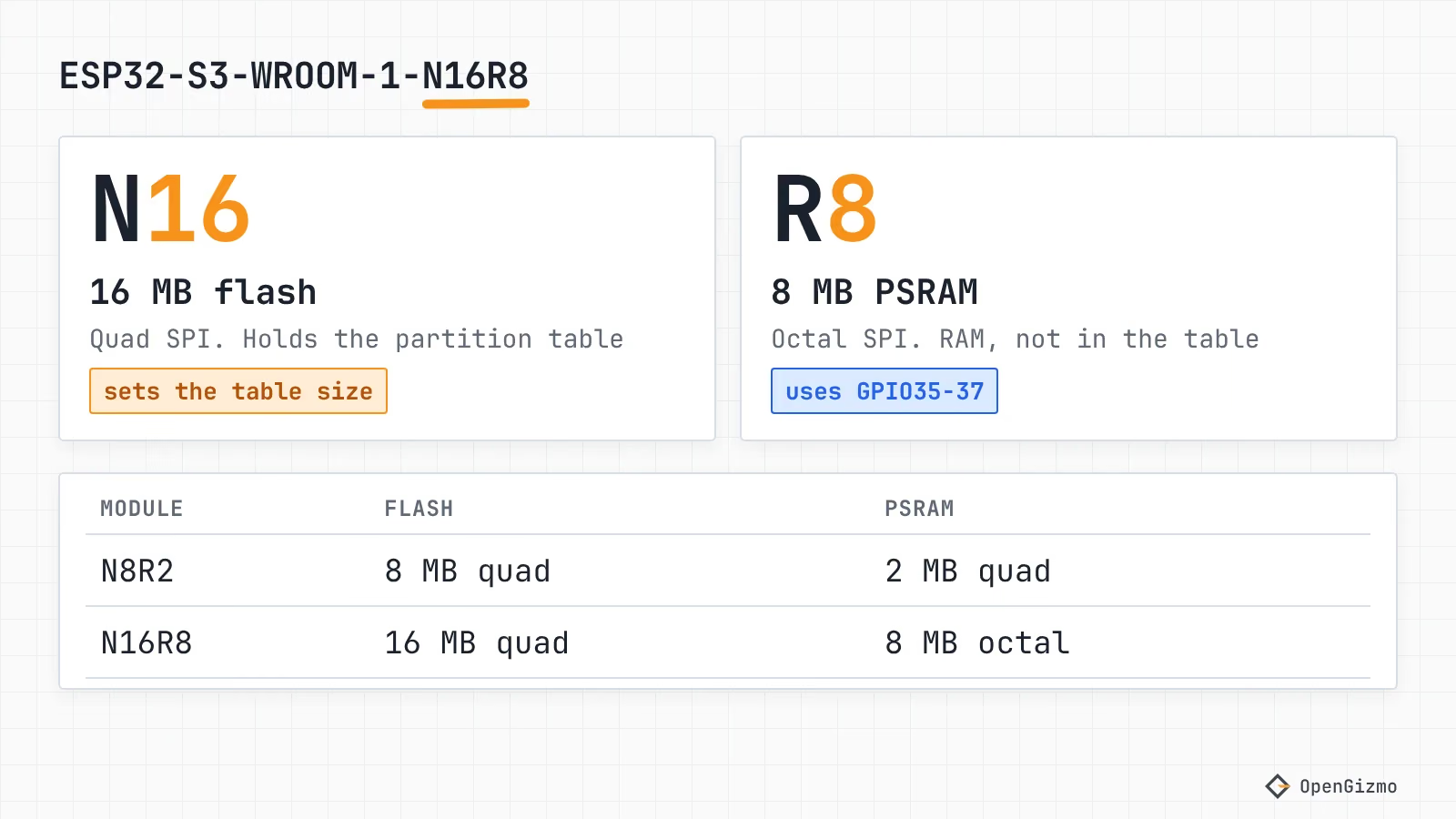
| Module | Flash (MB) | PSRAM (MB) | Table that fits |
|---|---|---|---|
| ESP32-S3-WROOM-1-N8R2 | 8, quad SPI | 2, quad SPI | default_8MB.csv |
| ESP32-S3-WROOM-1-N8R8 | 8, quad SPI | 8, octal SPI | default_8MB.csv |
| ESP32-S3-WROOM-1-N16R8 | 16, quad SPI | 8, octal SPI | default_16MB.csv |
Two practical points sit behind that table. First, the datasheet says that on modules with octal PSRAM (the R8 and R16V series) pins IO35, IO36 and IO37 are connected to the PSRAM and are not available for other uses, so an N16R8 loses three GPIOs that an N8R2 keeps. Second, "Table that fits" is my pairing, not Espressif's: any table works as long as it ends within the flash size. The esptool documentation warns that partitions must fit within the configured size, or the ESP32 will not work correctly.
The XIAO ESP32-S3 is a board, not a WROOM module, but Seeed's wiki lists the same pair of facts: the ESP32-S3R8 chip with 8 MB of PSRAM, and 8 MB of flash. For which chip to buy in the first place, see Which ESP32 should you buy? and the XIAO comparison.
How do you size app, OTA and filesystem partitions?
Work from the app size outward, and write the table down before you flash it.
- Measure the app. Build the firmware and read the size of the
.bin. For example, the Ticker's is 1,796,736 bytes. - Decide on OTA. For updates over Wi-Fi you need
otadataplus two app slots, per the ESP-IDF OTA docs as summarized in the OTA comparison. Each slot must hold the app with headroom for growth. - Keep
nvshonest. The NVS documentation gives 12 KiB (0x3000) as the minimum for normal read-write use. The Arduino tables use 0x5000 (20 KB). - Spend the rest on a filesystem, or drop it. If nothing mounts it, an unused
spiffsis wasted space you could give to the app slots. - Check the sum. The last partition must end at or before your flash size, and every app offset must be a multiple of 0x10000.
For example, an 8 MB board with two 3 MB slots and a small filesystem could use the table below. This is my own arithmetic, not a table I built or flashed, so treat it as a template:
nvs,      data, nvs,     0x9000,   0x5000,
otadata,  data, ota,     0xe000,   0x2000,
app0,     app,  ota_0,   0x10000,  0x300000,
app1,     app,  ota_1,   0x310000, 0x300000,
spiffs,   data, spiffs,  0x610000, 0x1E0000,
coredump, data, coredump,0x7F0000, 0x10000,The last row ends at 0x800000, exactly 8 MB. In Arduino IDE, save it as partitions.csv in the sketch folder and the build uses it instead of the predefined tables, as the Arduino-ESP32 partition tutorial describes. In PlatformIO, point board_build.partitions at the file.
Changing the table has a cost. ESP-IDF says updating it does not erase data stored under the old table. Since every partition is found by its offset, a moved or resized one will read whatever bytes now sit there (my reading of how offsets work, not a quote from the docs). Keep nvs where it is and the saved settings keep working; otherwise plan for a clean start.
How do you find the offsets and the flash size of a board?
Three commands cover it. The first two read your build and your chip, the third reads what is really on the board.
pio project metadata -e release --json-outputesptool flash-idesptool -p /dev/ttyACM0 read-flash 0x8000 0x1000 table.binpio project metadataprints the flash images with their addresses and the application offset. The Ticker'spackage_firmware.pyreads exactly that to write the manifest, so you never type an offset by hand.esptool flash-idprints the manufacturer, the device ID and the "Detected flash size", per the esptool basic commands. Run it before you pick a table for a board you did not buy yourself.read-flashcopies the table out of the board. The ESP-IDF guide documentsgen_esp32part.pyfor turning a binary table back into CSV, and I decoded the shipped files with my own short script instead.
Command names are the hyphenated forms the current esptool documentation uses, and older versions spelled them with underscores. Match them to the version you have installed.
What does the partition table decide for you?
The ESP32 partition table decides how a fixed flash chip is shared between your app, a possible second app, your settings and a filesystem. For OpenGizmo the answer is a deliberate one: huge_app.csv, one 3 MB slot, about 57% used by the biggest app, settings in nvs that a USB update never touches, and no OTA.
The limits are worth saying out loud. I read the tables and decoded the shipped binaries, but I did not flash a changed table to a board, so the custom CSV above is arithmetic, and the role of boot_app0 is an inference from its offset, size and first bytes. The next useful step is the OTA methods comparison, which shows what a second slot would cost this layout, or the Arduino IDE vs PlatformIO post if you are still choosing where to set the scheme.
Frequently asked questions
Find quick answers to the most common questions about this topic.
The ESP32 partition table is stored in flash at offset 0x8000 by default, according to the ESP-IDF documentation. It takes one 4 KB sector and holds up to 95 entries plus an MD5 checksum. The bootloader reads it at every boot to find the app and the data partitions.

Author
Mauro BrambillaReady to build your own gizmo?
Pick an open-source ESP32 project and follow its step-by-step guide, from the parts list and wiring to the firmware and the first boot.