MAX7219 FC16 With ESP32: Wiring, 3.3 V Logic, Mirroring
Wire a 4-in-1 FC16 MAX7219 matrix to an ESP32 with five wires, check the 3.3 V logic question, and fix mirrored text with the right MD_MAX72XX hardware type.
- Author
 Mauro Brambilla
- Published
- Reading time
- 10 min
- Category
- Builds
In short
An FC16 MAX7219 module needs five wires to an ESP32: 5 V, GND, DIN, CS and CLK. Pick FC16_HW in MD_MAX72XX; mirrored or reversed text means the hardware type does not match your board.
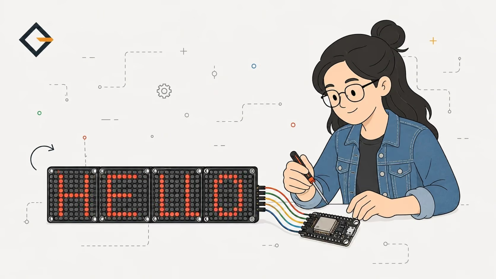
A 4-in-1 FC16 MAX7219 module connects to an ESP32 with five wires: 5 V, GND, DIN, CS and CLK. Drive it with the MD_MAX72XX library and set the hardware type to FC16_HW. If the text shows up mirrored, flipped or in the wrong order, the hardware type does not match your board, and changing it is the fix.
This is the focused reference behind the Gizmo Ticker, which runs an FC16 matrix on a XIAO ESP32-S3. The pins and library versions come from its firmware, the type table comes from the MD_MAX72XX source, and the parts measurements come from my part notes. The full build, with flashing and the API key, is in the crypto ticker build guide.
A WiFi-connected crypto display built with an ESP32, a MAX7219 LED matrix, and a Nuxt 4 web app for browser-based setup and configuration.
- Live crypto ticker
- MAX7219 LED matrix
- Web-based setup
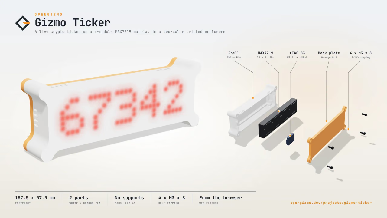
What is an FC16 MAX7219 4-in-1 module?
A MAX7219 is a driver chip that lights up to 64 LEDs, one 8x8 matrix, from a short serial bus, and it can be chained with other MAX7219s (Analog Devices product page). An FC16 module is the common board that chains four of them for you: four 8x8 red matrices, each with its own MAX7219, on one long PCB. The MD_MAX72XX documentation says you can recognize an FC-16 by the "FC-16" printed on the PCB, and that most sets of four modules sold as one unit are this type (FC-16 page).
On the one I use for the ticker, the PCB measures 132 x 32 mm, and the LED blocks cover the whole length, although four 32 mm blocks would add up to 128 mm. Sellers disagree on the length (128 to 132 mm), so measure yours before you design anything around it. The straight header pins stick out about 7 mm at each end. Those numbers come from my part notes for this board, measured and confirmed on the ticker's test prints.
How do you wire an ESP32 to a MAX7219 FC16 module?
You need the five pins of the input side of the module: VCC, GND, DIN, CS and CLK. The library names them like this: DIN is the serial data in, CLK clocks the data, and CS (called LD in the library's documentation) selects the whole chain, and the data is latched when it goes high again (library connection notes). The other side of the board has DOUT, which feeds the next module, so you leave it alone.
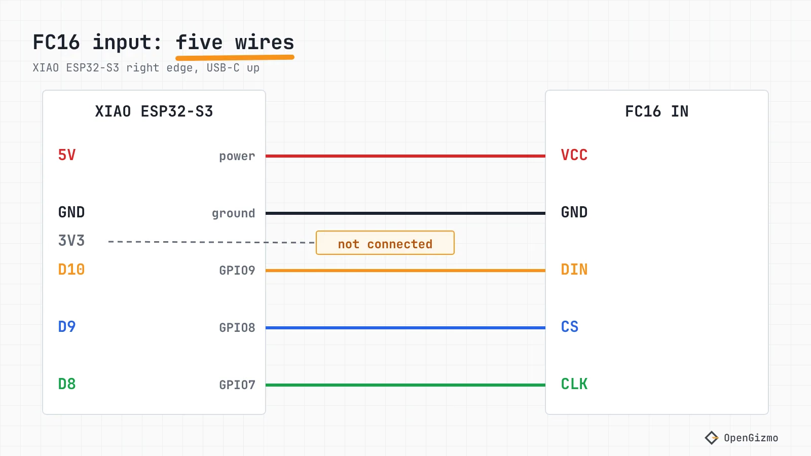
Here is the pin map the Gizmo Ticker uses. The GPIO numbers are the chip's own, and the D labels are the XIAO's pad names, explained in the XIAO ESP32-S3 pinout guide.
| FC16 input | XIAO ESP32-S3 pad | ESP32-S3 GPIO | Role |
|---|---|---|---|
| VCC | 5V | none | Matrix power |
| GND | GND | none | Ground |
| DIN | D10 | GPIO9 | SPI data out (MOSI) |
| CS | D9 | GPIO8 | Chip select |
| CLK | D8 | GPIO7 | SPI clock (SCK) |
The pads next to 5V and GND follow the order of the module input, so a flat cable runs straight across and the 3V3 wire stays free. On any other ESP32 board, pick any three free GPIOs: the library has a constructor that takes the data, clock and CS pins directly, and another that uses the board's hardware SPI. Hardware SPI is faster, and the library's own documentation describes the software version as slower.
Here is the real setup code of the ticker, from matrix.cpp:
SPI.begin(CLK_PIN, -1, DATA_PIN); // The display only writes: no MISO, so its default pin stays free (MD_MAX72XX then reuses this bus)
matrix = new MD_Parola(HARDWARE_TYPE, CS_PIN, config.matrixModules);
matrix->begin(); // Start the LED matrixTwo details matter. The -1 means "no MISO", because the display never sends anything back, and that frees D9 to act as CS. The HARDWARE_TYPE constant is MD_MAX72XX::FC16_HW, defined in config.h. The MD_MAX72XX 3.5.1 source starts each SPI transaction at 8 MHz in mode 0, which is under the 10 MHz clock limit in the MAX7219 datasheet but worth remembering if your wires are long.
If you are not on the XIAO, the same idea fits in a few lines. This minimal sketch follows the ticker's setup and the library's documented API, with the ticker's pins; I have not compiled this exact sketch, so treat it as a starting point and change the three pin numbers to your board's:
#include <MD_Parola.h>
#include <MD_MAX72xx.h>
#include <SPI.h>

constexpr MD_MAX72XX::moduleType_t HARDWARE_TYPE = MD_MAX72XX::FC16_HW;
constexpr uint8_t MODULES = 4; // one 4-in-1 board
constexpr uint8_t CS_PIN = 8;

MD_Parola display(HARDWARE_TYPE, CS_PIN, MODULES);

void setup() {
    SPI.begin(7, -1, 9); // SCK, no MISO, MOSI
    display.begin();
    display.setIntensity(1); // 0-15
    display.displayText("HELLO", PA_CENTER, 50, 1000, PA_SCROLL_LEFT, PA_SCROLL_LEFT);
}

void loop() {
    if (display.displayAnimate()) display.displayReset();
}Before celebrating, power the board and look for any text at all. A blank display with correct wiring is a different problem from mirrored text, and the next sections take them one at a time.
Does 3.3 V logic work with a 5 V MAX7219 board?
Usually yes in practice, but it is outside what the datasheet guarantees. The matrix runs from 5 V, while the ESP32's GPIOs signal at 3.3 V, so what matters is whether a 3.3 V high counts as a high to the MAX7219.
The numbers, from the primary sources:
| Source | Parameter | Value | Conditions |
|---|---|---|---|
| MAX7219 datasheet | Logic high input voltage (VIH), DIN, CLK, CS | 3.5 V minimum | V+ = 5 V, plus or minus 10% |
| MAX7219 datasheet | Logic low input voltage (VIL) | 0.8 V maximum | V+ = 5 V, plus or minus 10% |
| MAX7219 datasheet | Operating supply voltage | 4.0 to 5.5 V | none |
| ESP32-S3 datasheet v2.2 | High-level output voltage (VOH) | 0.8 x VDD minimum, 2.64 V at 3.3 V | VDD = 3.3 V, 25 C |
Both come from the manufacturers: the Espressif ESP32-S3 datasheet (table 5-4) and the Maxim MAX7219 datasheet, revision 4. Analog Devices' own page for it did not load when this post was checked, so I read the same revision from a copy hosted by SparkFun; the Analog Devices product page may list a newer one.
So the guaranteed ESP32-S3 high (2.64 V) is below the guaranteed MAX7219 minimum (3.5 V). The datasheets do not promise that this works. What the Gizmo Ticker does is clear from its repository: DIN, CS and CLK go straight from the XIAO's 3.3 V pins to the matrix, which sits on the 5V pad, with no level shifter. The README documents the wiring and gives no margin analysis, and I am not claiming a test beyond that. Real chips often switch below the guaranteed level, but you cannot count on it with a different batch, a long cable or a noisy supply.
If you see garbage, flicker or random pixels, put a level shifter on the three signal lines (DIN, CS, CLK). It only needs to work in one direction, because the display never talks back. The reverse risk does not exist in this wiring: the ESP32-S3's inputs tolerate at most VDD plus 0.3 V, but no wire carries data from the matrix to the ESP32. The same question comes up for a 5 V I2C backpack in ESP32 I2C LCD 16x2 not working. Check the supply too, as the ESP32 brownout guide explains.
Why is my MAX7219 text mirrored or reversed?
Every FC16-style board has the same chips, but the wiring between the LED matrix and the MAX7219 differs from one board family to another. The MD_MAX72XX documentation says the circuits are essentially the same and that the difference is how the matrix is wired to the chip, which the library handles in software with a moduleType_t value (hardware page).
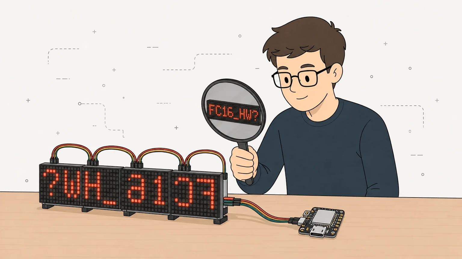
Each type is a combination of three switches, described in the structured names page: DR (digits as rows), CR (columns reversed) and RR (rows reversed). This is how the 3.5.1 source sets them in setModuleParameters():
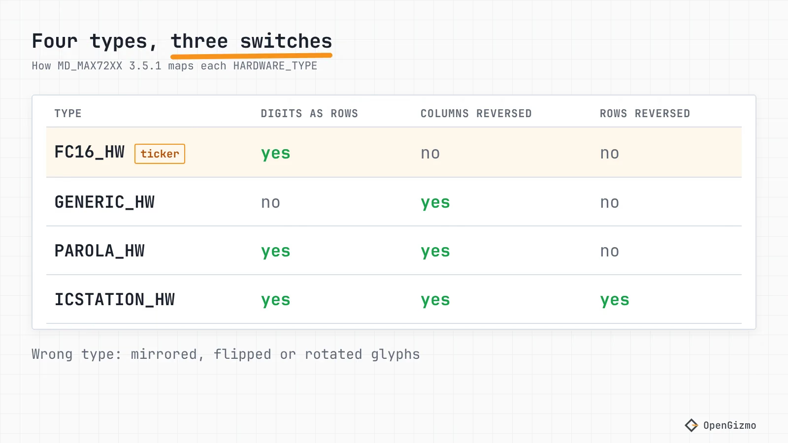
| Hardware type | Digits as rows (DR) | Columns reversed (CR) | Rows reversed (RR) | Structured name |
|---|---|---|---|---|
| FC16_HW | yes | no | no | DR1CR0RR0 |
| GENERIC_HW | no | yes | no | DR0CR1RR0 |
| PAROLA_HW | yes | yes | no | DR1CR1RR0 |
| ICSTATION_HW | yes | yes | yes | DR1CR1RR1 |
The column and row flips act on one 8x8 block at a time: the source maps a pixel to COL_SIZE - 1 - c and ROW_SIZE - 1 - r, where both sizes are 8. So they fix glyphs that are mirrored or flipped inside each block. The table below is my reading of those flags, not a bench test, so treat it as a short list of what to try first, one type per build.
| What you see | Which switch is probably off | Try this |
|---|---|---|
| Each letter mirrored left to right, upright | Columns reversed (CR) | Switch FC16_HW to PAROLA_HW, which differs only in CR |
| Each letter flipped top to bottom | Rows reversed (RR) | Use the structured name DR1CR0RR1_HW, which has no alias in the library |
| Each letter rotated 180 degrees | CR and RR together | Try ICSTATION_HW, which is FC16_HW with both flips added |
| Letters lying on their side or scrambled | Digits as rows (DR) | Try GENERIC_HW, then run the HW_Mapper example |
Module order is a separate question from the three flips. The library's FC-16 page says the display is oriented with the DIN side on the right, and the structured-names page says the modules are daisy chained from right to left. It also warns that the text printed on the PCB may appear upside down, so judge the board by what the LEDs show, not by its silkscreen. My parts notes assume the same DIN-on-the-right layout for the ticker and list it as still open: I have not confirmed it on every board. If whole words come out in the wrong module order, check that you fed the input pads (DIN) and not the output pads (DOUT), and that the module count in your code matches the number of modules.
If no named type works, the library ships a utility called MD_MAX72xx_HW_Mapper: run it with one module, and it prints which digit and segment each lit pixel belongs to, so you can build the right DR#CR#RR#_HW name. The library warns that combinations without an alias are not guaranteed to work unless tested.
Can you fix it in software instead? MD_Parola has PA_FLIP_UD and PA_FLIP_LR zone effects, set with setZoneEffect(). Its header says PA_FLIP_UD works with every text effect, but PA_FLIP_LR does not work with SCROLL_LEFT, SCROLL_RIGHT or SLICE, and the ticker scrolls left (PA_SCROLL_LEFT in config.cpp). For a scrolling display, a left-to-right mirror is fixed by the hardware type, not by a flip.
In the Gizmo Ticker, that means editing the HARDWARE_TYPE line in config.h and building the firmware yourself. The browser-flashed release is fixed to FC16_HW.
Why is my MAX7219 matrix blank, dim or showing garbage?
A blank or noisy FC16 display is almost always power, wiring or a mismatch between the code and the board, and the order below goes from the cheapest check to the most work. Change one thing at a time.
| What you see | Likely cause | What to check |
|---|---|---|
| Nothing lights up | No power, no common ground or the wrong end wired | 5 V on VCC, GND joined to the ESP32, wires on the input pads, not DOUT |
| Nothing lights up, wiring looks right | CS or module count differs from the code | The CS pin in the constructor matches the CS wire, and the module count is 4 per board |
| Very faint text | Intensity set low | setIntensity() takes 0 to 15, and the ticker's default is 1 |
| Random pixels, flicker or garbage | Marginal 3.3 V logic or a weak supply | Level shifter on DIN, CS and CLK, shorter wires, a stable 5 V supply |
| Text is readable but mirrored or flipped | Wrong hardware type | The symptom table in the mirroring section above, one type at a time |
The MAX7219 datasheet gives an operating supply of 4.0 to 5.5 V, so a matrix wired to the 3V3 pad is below its range. The ticker keeps that pad free for the same reason. The ESP32 brownout guide covers the case where the whole board resets instead.
How do you chain MAX7219 modules, and how much current is that?
A chain is a shift register line: DOUT of one module goes to DIN of the next, while CS and CLK are shared by all of them. The library's connection notes say data is shifted into a 16-bit register and latched on the rising edge of the load signal, and that the CS line selects the whole chain. An FC16 board already chains its four modules; to extend the display, join the output pads of one board to the input pads of the next.
You tell the library how many 8x8 modules there are, and the rest follows. The Gizmo Ticker stores that number in flash and accepts 4 to 32 in steps of 4, because the boards come as 4-in-1. Its default is 4, one board, which is also what the enclosure is drawn for. The firmware restarts after you change the count, since the display object is created once at boot.
On current I have no measured number for the FC16 board. The ticker repository states none, and my parts notes do not list one. The MAX7219 datasheet gives a worst case for one chip: up to 330 mA with every segment on at 40 mA, and an FC16 board has four chips, so the ceiling multiplies, but the real draw depends on the brightness setting and on the board's own current-set resistor. The library documentation only says the supply must provide enough current for the connected modules. What I can say from the firmware: brightness is the setIntensity() setting, 0 to 15, and the ticker defaults to 1. If you chain more boards, measure the draw with a USB power meter at your brightness before you trust a laptop port, and read the brownout guide if the board resets when the display gets bright. I would feed long chains from a proper 5 V supply with the grounds joined, but that is my preference, not something I tested.
Which library should you pick for an ESP32 MAX7219 display?
Two libraries from the same author, one on top of the other. MD_MAX72XX talks to the chips and treats the chain as one pixel surface: set a pixel, draw a bitmap, change the intensity. MD_Parola builds text on top of it: scrolling, alignment, pauses and animations, and it needs MD_MAX72XX installed. The ticker uses MD_Parola 3.7.5 and MD_MAX72XX 3.5.1, pinned in platformio.ini, because text is all it shows.
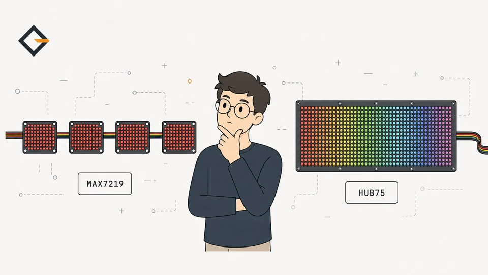
For text, start with MD_Parola. For graphics, a game or a custom animation, use MD_MAX72XX directly. Both take the same moduleType_t argument, so everything above applies to either. If you are still deciding between this kind of display and a bigger panel, MAX7219 vs HUB75 compares them.
What did we verify, and what is still open?
You now have the five-wire map for an FC16 module on a XIAO ESP32-S3, the code that starts it, and a table that turns "my text is mirrored" into the next type to try. The pins, the pinned library versions and the 8 MHz SPI setting come from the ticker and library sources. The 2.64 V output level comes from Espressif's datasheet, and the 3.5 V input level from the MAX7219 datasheet, revision 4.
Three limits remain. The 3.3 V wiring works in the ticker but sits below the datasheet's guaranteed input level, so a level shifter is the safe fix when it misbehaves. The symptom table follows from the library's flags and has not been run on every board family. And chain length and current are untested here beyond one 4-in-1 board. To see the whole device built around this matrix, read the crypto ticker build, and CoinGecko API on ESP32: free limits and polling rate for how its prices are fetched. See also what OpenGizmo is for the other projects.
Frequently asked questions
Find quick answers to the most common questions about this topic.
Use FC16_HW in the MD_MAX72XX library for the common 4-in-1 boards with FC-16 printed on the PCB. The Gizmo Ticker firmware sets exactly that. If the text still appears mirrored or flipped, try PAROLA_HW, GENERIC_HW or ICSTATION_HW one at a time and rebuild.

Author
Mauro BrambillaReady to build your own gizmo?
Pick an open-source ESP32 project and follow its step-by-step guide, from the parts list and wiring to the firmware and the first boot.